CCNA 4 Final Exam Answer v5 -v5.02 2015

CCNA 4 Final Exam Answer v5 -v5.02 2015

this article only for review and showing how will be the exams

this article taken from here

CCNA 4 Final Exam Answer v5 & v5.02 2015 (100%)


  1. Which two statements about DSL are true? (Choose two.)

    • users are on a shared medium
    • uses RF signal transmission
    • local loop can be up to 3.5 miles (5.5km)
    • physical and data link layers are defined by DOCSIS
    • user connections are aggregated at a DSLAM located at the CO

  2. Which two statements are true regarding a PPP connection between two Cisco routers? (Choose two.)

    • LCP tests the quality of the link.
    • LCP manages compression on the link.
    • Only a single NCP is allowed between the two routers.
    • NCP terminates the link when data exchange is complete.
    • With CHAP authentication, the routers exchange plain text passwords.

  3. A network administrator is asked to design a system to allow simultaneous access to the Internet for 250 users. The ISP can only supply five public IP addresses for this network. What technology can the administrator use to accomplish this task?

    • classful subnetting
    • variable length subnet masks
    • classless interdomain routing
    • port-based Network Address Translation

  4. Refer to the exhibit. An administrator is configuring NAT to provide Internet access to the inside network. After the configuration is completed, users are unable to access the Internet. What is the cause of the problem?CCNA4_Final_Exam_01

    • The NAT pool is using an invalid address range.
    • The inside and outside interfaces are backwards.
    • The ACL is referencing the wrong network address.
    • The NAT inside source command is referring to the wrong ACL.

  5. What is the expected behavior of an ADSL service?

    • The download rate is faster than the upload rate.
    • The upload rate is faster than the download rate.
    • The download and upload rates are the same.
    • The user can select the upload and download rates based on need.

  6. A network administrator is troubleshooting the dynamic NAT that is configured on router R2. Which command can the administrator use to see the total number of active NAT translations and the number of addresses that are allocated from the NAT pool?

    • R2# show ip nat statistics
    • R2# show ip nat translations
    • R2# show running-config
    • R2# clear ip nat translation

  7. Which type of traffic would most likely have problems when passing through a NAT device?

    • Telnet
    • IPsec
    • HTTP
    • ICMP
    • DNS

  8. Refer to the exhibit. The inside local IP address of PC-A is 192.168.0.200. What will be the inside global address of packets from PC-A after they are translated by R1?CCNA4_Final_Exam_02

    • 10.0.0.1
    • 172.16.0.1
    • 192.168.0.1
    • 192.168.0.200
    • 209.165.200.225

  9. Refer to the exhibit. What kind of NAT is being configured on R1?CCNA4_Final_Exam_03

    • PAT
    • dynamic NAT
    • NAT overload
    • port forwarding

  10. What benefit does NAT64 provide?

    • It allows sites to use private IPv6 addresses and translates them to global IPv6 addresses.
    • It allows sites to connect multiple IPv4 hosts to the Internet via the use of a single public IPv4 address.
    • It allows sites to connect IPv6 hosts to an IPv4 network by translating the IPv6 addresses to IPv4 addresses.
    • It allows sites to use private IPv4 addresses, and thus hides the internal addressing structure from hosts on public IPv4 networks.

  11. What are three benefits of using Frame Relay for WAN connectivity? (Choose three.)

    • QoS support using the IP precedence field
    • one physical interface that can be used for several circuits
    • integrated encryption
    • mature technology
    • reasonable cost
    • seamless direct connectivity to an Ethernet LAN

  12. The DLCI number assigned to a Frame Relay circuit is to be manually added on a point-to-point link. Which three subinterface commands could be used to complete the configuration? (Choose three.)

    • bandwidth kilobits
    • encapsulation frame-relay
    • frame-relay interface-dlci dlci
    • frame-relay map ip ip-address dlci
    • frame-relay map ip ip-address dlci broadcast
    • ip address ip-address mask
    • no shutdown

  13. Which command can be used to check the information about congestion on a Frame Relay link?

    • show frame-relay pvc
    • show frame-relay lmi
    • show interfaces
    • show frame-relay map

  14. A network administrator is configuring a PPP link with the commands:

    R1(config-if)# encapsulation ppp
    R1(config-if)# ppp quality 70

    What is the effect of these commands?

    • The PPP link will be closed down if the link quality drops below 70 percent.
    • The NCP will send a message to the sending device if the link usage reaches 70 percent.
    • The LCP establishment phase will not start until the bandwidth reaches 70 percent or more.
    • The PPP link will not be established if more than 30 percent of options cannot be accepted.

  15. Refer to the exhibit. A network administrator has implemented the configuration in the displayed output. What is missing from the configuration that would be preventing OSPF routing updates from passing to the Frame Relay service provider?CCNA4_Final_Exam_04

    • The passive-interface command has not been issued on interface serial 0/1/0.
    • The broadcast keyword has not been issued.
    • The directly connected neighbor should have been identified by using static mapping.
    • The command to disable split horizon has not been issued.

  16. What is a characteristic of Frame Relay that allows customer data transmissions to dynamically “burst” over their CIR for short periods of time?

    • The combination of LMI status messages and Inverse ARP messages enables the CIR to be exceeded.
    • The physical circuits of the Frame Relay network are shared between subscribers and there may be times when unused bandwidth is available.
    • Bursting is enabled by the configuration of multiple subinterfaces on one physical interface.
    • BECN and FECN messages notify the router that the CIR can be exceeded.

  17. Which broadband technology would be best for a small office that requires fast upstream connections?

    • DSL
    • fiber-to-the-home
    • cable
    • WiMax

  18. What is the protocol that provides ISPs the ability to send PPP frames over DSL networks?

    • PPPoE
    • CHAP
    • ADSL
    • LTE

  19. Which technology requires the use of PPPoE to provide PPP connections to customers?

    • dialup analog modem
    • dialup ISDN modem
    • DSL
    • T1

  20. Why is it useful to categorize networks by size when discussing network design?

    • Knowing the number of connected devices will define how many multilayer switches will be necessary at the core layer​.
    • Knowing the number of connected devices will define how many additional layers will be added to the three-tier hierarchical network design​.
    • A high-level redundancy at the access layer may be better implemented if the number of connected devices is known.​
    • The complexity of networking infrastructure will vary according to the number of connected devices.

  21. Why is it useful to categorize networks by size when discussing network design?

    • Knowing the number of connected devices will define how many multilayer switches will be necessary at the core layer​.
    • Knowing the number of connected devices will define how many additional layers will be added to the three-tier hierarchical network design​.
    • A high-level redundancy at the access layer may be better implemented if the number of connected devices is known.​
    • The complexity of networking infrastructure will vary according to the number of connected devices.

  22. A company connects to one ISP via multiple connections. What is the name given to this type of connection?

    • single-homed
    • multihomed
    • dual-multihomed
    • dual-homed

  23. What is one advantage to designing networks in building block fashion for large companies?

    • failure isolation
    • increased network access time
    • coarse security control
    • fewer required physical resources

  24. Which network module maintains the resources that employees, partners, and customers rely on to effectively create, collaborate, and interact with information?

    • access-distribution
    • services
    • data center
    • enterprise edge

  25. A group of Windows PCs in a new subnet has been added to an Ethernet network. When testing the connectivity, a technician finds that these PCs can access local network resources but not the Internet resources. To troubleshoot the problem, the technician wants to initially confirm the IP address and DNS configurations on the PCs, and also verify connectivity to the local router. Which three Windows CLI commands and utilities will provide the necessary information? (Choose three.)

    • arp -a
    • ipconfig
    • nslookup
    • ping
    • telnet
    • tracert
    • netsh interface ipv6 show neighbor

  26. A team of engineers has identified a solution to a significant network problem. The proposed solution is likely to affect critical network infrastructure components. What should the team follow while implementing the solution to avoid interfering with other processes and infrastructure?

    • change-control procedures
    • one of the layered troubleshooting approaches
    • knowledge base guidelines
    • syslog messages and reports

  27. Which troubleshooting tool would a network administrator use to check the Layer 2 header of frames that are leaving a particular host?

    • protocol analyzer
    • baselining tool
    • knowledge base
    • CiscoView

  28. Which two specialized troubleshooting tools can monitor the amount of traffic that passes through a switch? (Choose two.)

    • TDR
    • digital multimeter
    • NAM
    • portable network analyzer
    • DTX cable analyzer

  29. Refer to the exhibit. Which two statements describe the results of entering these commands? (Choose two.)CCNA4_Final_Exam_05

    • R1 will send system messages of levels 0 (emergencies) to level 4 (warnings) to a server.
    • R1 will not send critical system messages to the server until the command debug all is entered.
    • R1 will reset all the warnings to clear the log.
    • R1 will output the system messages to the local RAM.
    • The syslog server has the IPv4 address 192.168.10.10.

  30. Refer to the exhibit. On the basis of the output, which two statements about network connectivity are correct? (Choose two.)CCNA4_Final_Exam_06

    • There is connectivity between this device and the device at 192.168.100.1.
    • The connectivity between these two hosts allows for videoconferencing calls.
    • There are 4 hops between this device and the device at 192.168.100.1.
    • The average transmission time between the two hosts is 2 miliseconds.
    • This host does not have a default gateway configured.

  31. Which statement is a characteristic of SNMP MIBs?

    • The MIB organizes variables in a flat manner.
    • The SNMP agent uses the SNMP manager to access information within the MIB.​
    • The NMS must have access to the MIB in order for SNMP to operate properly.
    • The MIB structure for a given device includes only variables that are specific to that device or vendor.​

  32. Refer to the exhibit. Router R1 was configured by a network administrator to use SNMP version 2. The following commands were issued:

    R1(config)# snmp-server community batonaug ro SNMP_ACL
    R1(config)# snmp-server contact Wayne World
    R1(config)# snmp-server host 192.168.1.3 version 2c batonaug
    R1(config)# ip access-list standard SNMP_ACL
    R1(config-std-nacl)# permit 192.168.10.3

    Why is the administrator not able to get any information from R1?CCNA4_Final_Exam_07

    • The snmp-server enable traps command is missing.​
    • The snmp-server community command needs to include the rw keyword.​
    • There is a problem with the ACL configuration.
    • The snmp-server location command is missing.​

  33. What is used as the default event logging destination for Cisco routers and switches?

    • terminal line
    • syslog server
    • console line
    • workstation

  34. In the data gathering process, which type of device will listen for traffic, but only gather traffic statistics?

    • NMS
    • syslog server
    • NetFlow collector
    • SNMP agent

  35. Which SNMP message type informs the network management system (NMS) immediately of certain specified events?

    • GET request
    • SET request
    • GET response
    • Trap

  36. Which three flows associated with consumer applications are supported by NetFlow collectors? (Choose three.)

    • bandwidth regulation
    • accounting
    • billing
    • quality of service
    • error correction
    • network monitoring

  37. Which algorithm is considered insecure for use in IPsec encryption?

    • 3DES
    • AES
    • RSA
    • SHA-1

  38. Which statement describes a characteristic of dense wavelength division multiplexing (DWDM)?​

    • It supports the SONET standard, but not the SDH standard​.
    • It enables bidirectional communications over one pair of copper cables.
    • It can be used in long-range communications, like connections between ISPs.
    • It assigns incoming electrical signals to specific frequencies.

  39. Two corporations have just completed a merger. The network engineer has been asked to connect the two corporate networks without the expense of leased lines. Which solution would be the most cost effective method of providing a proper and secure connection between the two corporate networks?

    • Cisco AnyConnect Secure Mobility Client with SSL
    • Cisco Secure Mobility Clientless SSL VPN
    • Frame Relay
    • remote access VPN using IPsec
    • site-to-site VPN

  40. Refer to the exhibit. Which IP address is configured on the physical interface of the CORP router?CCNA4_Final_Exam_08

    • 10.1.1.1
    • 10.1.1.2
    • 209.165.202.133
    • 209.165.202.134

  41. What are three characteristics of the generic routing encapsulation (GRE) protocol? (Choose three.)

    • GRE tunnels support multicast traffic.
    • By default, GRE does not include any flow control mechanisms.
    • Developed by the IETF, GRE is a secure tunneling protocol that was designed for Cisco routers.
    • GRE uses AES for encryption unless otherwise specified.
    • GRE creates additional overhead for packets that are traveling through the VPN.
    • GRE provides encapsulation for a single protocol type that is traveling through the VPN.

  42. Which WAN technology can serve as the underlying network to carry multiple types of network traffic such as IP, ATM, Ethernet, and DSL?

    • ISDN
    • MPLS
    • Frame Relay
    • Ethernet WAN

  43. Which two statements describe remote access VPNs? (Choose two.)

    • Remote access VPNs are used to connect entire networks, such as a branch office to headquarters.
    • End users are not aware that VPNs exists.
    • A leased line is required to implement remote access VPNs.
    • Client software is usually required to be able to access the network.
    • Remote access VPNs support the needs of telecommuters and mobile users.

  44. Which circumstance would result in an enterprise deciding to implement a corporate WAN?

    • when its employees become distributed across many branch locations
    • when the network will span multiple buildings
    • when the number of employees exceeds the capacity of the LAN
    • when the enterprise decides to secure its corporate LAN

  45. An intercity bus company wants to offer constant Internet connectivity to the users traveling on the buses. Which two types of WAN infrastructure would meet the requirements? (Choose two.)

    • private infrastructure
    • public infrastructure
    • dedicated
    • circuit-switched
    • cellular

  46. Under which two categories of WAN connections does Frame Relay fit? (Choose two.)

    • public infrastructure
    • private infrastructure
    • dedicated
    • Internet
    • packet-switched

  47. What term is used to identify the point where the customer network ends and the service provider network begins?

    • CSU/DSU
    • the central office
    • the local loop
    • the demarcation point

  48. Which two characteristics describe time-division multiplexing? (Choose two.)

    • Traffic is allocated bandwidth across a single wire based on preassigned time slots.
    • Bandwidth is allocated to channels based on whether a station has data to transmit.
    • Encoding technology provides high data throughput in a minimum RF spectrum by supporting parallel data transmission.
    • Depending on the configured Layer 2 protocol, data is transmitted across two or more channels via the use of time slots.
    • Data capacity across a single link increases as bits from multiple sources are transmitted using interleaved slices of time.

  49. A branch office uses a leased line to connect to the corporate network. The lead network engineer confirms connectivity between users in the branch office, but none of the users can access corporate headquarters. System logs indicate that nothing has changed in the branch office network. What should the engineer consider next to resolve this network outage?

    • The network technician for the branch office should troubleshoot the switched infrastructure.
    • The system administrator in the branch office should reconfigure the default gateway on the user PCs.
    • The server administrator in the branch office should reconfigure the DHCP server.
    • The service provider for the branch office should troubleshoot the issue starting from the point of demarcation.

  50. Refer to the exhibit. Which three steps are required to configure Multilink PPP on the HQ router? (Choose three.)CCNA4_Final_Exam_09

    • Assign the serial interfaces to the multilink bundle.
    • Assign the Fast Ethernet interface to the multilink bundle.
    • Enable PPP encapsulation on the multilink interface.
    • Enable PPP encapsulation on the serial interfaces.
    • Bind the multilink bundle to the Fast Ethernet interface.
    • Create and configure the multilink interface.

  51. Refer to the exhibit. A network administrator discovers that host A is having trouble with Internet connectivity, but the server farm has full connectivity. In addition, host A has full connectivity to the server farm. What is a possible cause of this problem?CCNA4_Final_Exam_10

    • The router has an incorrect gateway.
    • Host A has an overlapping network address.
    • Host A has an incorrect default gateway configured.
    • Host A has an incorrect subnet mask.
    • NAT is required for the host A network.

  52. Refer to the exhibit. H1 can only ping H2, H3, and the Fa0/0 interface of router R1. H2 and H3 can ping H4 and H5. Why might H1 not be able to successfully ping H4 and H5?CCNA4_Final_Exam_11

    • Router R1 does not have a route to the destination network.
    • Switch S1 does not have an IP address configured.
    • The link between router R1 and switch S2 has failed.
    • Host H1 does not have a default gateway configured.
    • Hosts H4 and H5 are members of a different VLAN than host H1.

  53. What is required for a host to use an SSL VPN to connect to a remote network device?

    • VPN client software must be installed.
    • A site-to-site VPN must be preconfigured.
    • A web browser must be installed on the host.
    • The host must be connected to a wired network.

  54. What type of information is collected by Cisco NetFlow?

    • interface errors
    • CPU usage
    • memory usage
    • traffic statistics

  55. Match the characteristic to the appropriate authentication protocol. (Not all options are used.)

CCNA4_Final_Exam_001

CCNA 4 Final Exam Answer v5 -v5.02 2015

EIGRP Case Study

EIGRP Case Study

the source is from here

EIGRP

Instructions

Plan, design, and implement the complex international Travel Agency (ITA) EIGRP network based on the above diagram and following specifications.

Implement the design in the lab set of routers; verify that all configurations are operational and functioning according to the guidelines.

 Scenario

The ITA needs its core network set up with EIGRP with the following specifications. It has also recently acquired Local Travel Agency, which was running OSPF. Use the addressing scheme shown in the diagram.

  • The ITA core network is running EIGRP in AS 1.
  • Summarize the loopback interfaces on R2 with the best possible summary to the other EIGRP routers
  • Loopback 192 on R3 represents a connection to the Internet. Originate a default route into EIGRP from R3.
  • The Local Travel Agency router, R4, needs to communicate with the ITA core via OSPF area 0.
  • Redistribute OSPF into EIGRP.
  • Originate a default route into the OSPF process from R3.
  • Configure R2 to act as a DHCP server on the Ethernet subnet between R2 and R3.

Solution

1.     The ITA core network is running EIGRP in AS 1.

Router R1 Configuration

To rename router name from router to R1

Router(config)#hostname R1

To configure Loopback address

R1(config)#interface loo

R1(config)#interface loopback 1

R1(config-if)#ip add

R1(config-if)#ip address 192.168.1.1 255.255.255.252

R1(config-if)#no shut

R1(config-if)#no shutdown

R1(config-if)#exit

To configure Interface S0/0

R1(config-if)#ip add

R1(config-if)#ip address 192.168.1.129 255.255.255.252

R1(config-if)#clock

R1(config-if)#clock ra

R1(config-if)#clock rate 64000

R1(config-if)#no shutdown

R1(config-if)#exit

To configure interface s0/1

R1(config-if)#interface s0/1

R1(config-if)#ip add

R1(config-if)#ip address 192.168.1.133 255.255.255.252

R1(config-if)#no shutdown

R1(config-if)#

To Configure EIGRP on this router

Option 1

R1(config)#router eigrp 1

R1(config-router)#network 192.168.1.0

R1(config-router)#no auto

R1(config-router)#no auto-summary

R1(config-router)#exit

R1(config)#

Option 2 by using Wild Card Mask

R1(config)#router eigrp 1

R1(config-router)#network 192.168.1.0 0.0.0.3

R1(config-router)#network 192.168.1.128 0.0.0.3

R1(config-router)#network 192.168.1.130 0.0.0.3

R1(config-router)#no auto

R1(config-router)#no auto-summary

R1(config-router)#exit

R1(config)#

Router R2 Configuration

To rename router name from router to R2

Router(config)#hostname R2

To configure Loopback address

R2(config)#interface loopback 101

R2(config-if)#ip add 192.168.1.101 255.255.255.252

R2(config-if)#no shutdown

R2(config-if)#interface loopback 105

R2(config-if)#ip add 192.168.1.105 255.255.255.252

R2(config-if)#no shutdown

R2(config-if)#interface loopback 109

R2(config-if)#ip add 192.168.1.109 255.255.255.252

R2(config-if)#no shutdown

R2(config-if)#interface loopback 113

R2(config-if)#ip add 192.168.1.113 255.255.255.252

R2(config-if)#no shutdown

R2(config-if)#

To configure Interface S0/0

R2(config-if)#interface s0/0

R2(config-if)#ip add

R2(config-if)#ip address 192.168.1.130 255.255.255.252

R2(config-if)#no shut

R2(config-if)#no shutdown

R2(config-if)#exit

R2(config)#int

To configure Interface f0/0

R2(config)#interface f0/0

R2(config-if)#ip add

R2(config-if)#ip address 192.168.1.161 255.255.255.224

R2(config-if)#no shut

R2(config-if)#

To Configure EIGRP on this router

R2(config)#router eigrp 1

R2(config-router)#network 192.168.1.101 0.0.0.3

R2(config-router)#network 192.168.1.105 0.0.0.3

R2(config-router)#network 192.168.1.109 0.0.0.3

R2(config-router)#network 192.168.1.113 0.0.0.3

R2(config-router)#network 192.168.1.128 0.0.0.3

R2(config-router)#network 192.168.1.160 0.0.0.31

R2(config-router)#no auto-summary

R2(config-router)#

Router R3 Configuration

To rename router name from router to R3

Router(config)#hostname R3

To configure Loopback address

R3(config)#interface loopback 5

R3(config-if)#ip add

R3(config-if)#ip address 192.168.1.5 255.255.255.252

R3(config-if)#no sh

R3(config-if)#no shutdown

R3(config-if)#interface loopback 192

R3(config-if)#ip address 192.168.100.1 255.255.255.252

R3(config-if)#no shutdown

R3(config-if)#

To configure Interface S0/0

R3(config)#interface s0/0

R3(config-if)#ip add

R3(config-if)#ip address 192.168.1.134 255.255.255.252

R3(config-if)#clo

R3(config-if)#clock r

R3(config-if)#clock rate 64000

R3(config-if)#no shutdown

R3(config-if)#

To configure Interface f0/0

R3(config-if)#interface f0/0

R3(config-if)#ip add

R3(config-if)#ip address 192.168.1.162 255.255.255.224

R3(config-if)#no shut

R3(config-if)#no shutdown

R3(config-if)#

To configure Interface S0/1

R3(config-if)#interface s0/1

R3(config-if)#ip add

R3(config-if)#ip address 10.1.1.3 255.255.255.228

Bad mask 0xFFFFFFE4 for address 10.1.1.3

R3(config-if)#no shut

R3(config-if)#no shutdown

R3(config-if)#

R3(config-if)#clock rate 64000

R3(config-if)#no shutdown

R3(config-if)#

To Configure EIGRP on this router

R3(config)#router eigrp 1

R3(config-router)#network 192.168.1.160 0.0.0.31

R3(config-router)#network 192.168.1.132 0.0.0.3

R3(config-router)#network 192.168.1.5 0.0.0.3

R3(config-router)#exit

R3(config)#exit

R3#w


2.     Summarize the loopback interfaces on R2 with the best possible summary to the other EIGRP routers

Summarize the loopback interfaces on R2

R2(config-if)#interface s0/0

R2(config-if)#ip summary-address eigrp 1 192.168.1.101 255.255.255.240 5

R2(config-if)#

*Mar  1 00:14:21.691: %DUAL-5-NBRCHANGE: IP-EIGRP(0) 1: Neighbor 192.168.1.129 (Serial0/0) is down: summary configured

R2(config-if)#

*Mar  1 00:14:24.399: %DUAL-5-NBRCHANGE: IP-EIGRP(0) 1: Neighbor 192.168.1.129 (Serial0/0) is up: new adjacency

R2(config-if)#exit

R2(config)#interface f0/0

R2(config-if)#ip summary-address eigrp 1 192.168.1.101 255.255.255.240 5

R2(config-if)#exit

Show IP route on router R1

Before Summarize the loopback interfaces on R2

R1#sh ip route

Codes: C – connected, S – static, R – RIP, M – mobile, B – BGP

D – EIGRP, EX – EIGRP external, O – OSPF, IA – OSPF inter area

N1 – OSPF NSSA external type 1, N2 – OSPF NSSA external type 2

E1 – OSPF external type 1, E2 – OSPF external type 2

i – IS-IS, su – IS-IS summary, L1 – IS-IS level-1, L2 – IS-IS level-2

ia – IS-IS inter area, * – candidate default, U – per-user static route

o – ODR, P – periodic downloaded static route

Gateway of last resort is not set

192.168.1.0/24 is variably subnetted, 7 subnets, 2 masks

D       192.168.1.104/30 [90/2297856] via 192.168.1.130, 00:01:13, Serial0/0

D       192.168.1.108/30 [90/2297856] via 192.168.1.130, 00:01:13, Serial0/0

D       192.168.1.100/30 [90/2297856] via 192.168.1.130, 00:01:13, Serial0/0

D       192.168.1.112/30 [90/2297856] via 192.168.1.130, 00:01:13, Serial0/0

C       192.168.1.0/30 is directly connected, Loopback1

D       192.168.1.160/27 [90/2172416] via 192.168.1.130, 00:01:13, Serial0/0

C       192.168.1.128/30 is directly connected, Serial0/0

R1#

After Summarize the loopback interfaces on R2

R1#sh ip route

Codes: C – connected, S – static, R – RIP, M – mobile, B – BGP

D – EIGRP, EX – EIGRP external, O – OSPF, IA – OSPF inter area

N1 – OSPF NSSA external type 1, N2 – OSPF NSSA external type 2

E1 – OSPF external type 1, E2 – OSPF external type 2

i – IS-IS, su – IS-IS summary, L1 – IS-IS level-1, L2 – IS-IS level-2

ia – IS-IS inter area, * – candidate default, U – per-user static route

o – ODR, P – periodic downloaded static route

Gateway of last resort is not set

192.168.1.0/24 is variably subnetted, 5 subnets, 3 masks

D       192.168.1.96/28 [90/2297856] via 192.168.1.130, 00:01:05, Serial0/0

D       192.168.1.112/30 [90/2297856] via 192.168.1.130, 00:01:05, Serial0/0

C       192.168.1.0/30 is directly connected, Loopback1

D       192.168.1.160/27 [90/2172416] via 192.168.1.130, 00:01:05, Serial0/0

C       192.168.1.128/30 is directly connected, Serial0/0

R1#


3.     Loopback 192 on R3 represents a connection to the Internet. Originate a default route into EIGRP from R3.

Injecting a Default Route into EIGRP: IP Default Network

Specifies which network to advertise in EIGRP.

R3(config)#router eigrp 1

R3(config-router)#netwo

R3(config-router)#network 192.168.100.0

R3(config-router)#exit

Creates a static default route to send all traffic with a destination network not in the routing table to the exit interface

R3(config)#ip route 0.0.0.0 0.0.0.0 loopback 192

Defines a route to the 192.168.100.0 network as a candidate default route.

R3(config)#ip default-network 192.168.100.0

R3(config)#exit

R1#sh ip route

Codes: C – connected, S – static, R – RIP, M – mobile, B – BGP

D – EIGRP, EX – EIGRP external, O – OSPF, IA – OSPF inter area

N1 – OSPF NSSA external type 1, N2 – OSPF NSSA external type 2

E1 – OSPF external type 1, E2 – OSPF external type 2

i – IS-IS, su – IS-IS summary, L1 – IS-IS level-1, L2 – IS-IS level-2

ia – IS-IS inter area, * – candidate default, U – per-user static route

o – ODR, P – periodic downloaded static route

Gateway of last resort is 192.168.1.134 to network 192.168.100.0

192.168.1.0/24 is variably subnetted, 7 subnets, 3 masks

D       192.168.1.96/28 [90/2297856] via 192.168.1.130, 00:11:10, Serial0/0

D       192.168.1.112/30 [90/2297856] via 192.168.1.130, 00:11:10, Serial0/0

C       192.168.1.0/30 is directly connected, Loopback1

D       192.168.1.4/30 [90/2297856] via 192.168.1.134, 00:10:54, Serial0/1

D       192.168.1.160/27 [90/2172416] via 192.168.1.130, 00:11:10, Serial0/0

[90/2172416] via 192.168.1.134, 00:11:10, Serial0/1

C       192.168.1.128/30 is directly connected, Serial0/0

C       192.168.1.132/30 is directly connected, Serial0/1

D*   192.168.100.0/24 [90/2297856] via 192.168.1.134, 00:02:47, Serial0/1

R1#

R2#sh ip route

Codes: C – connected, S – static, R – RIP, M – mobile, B – BGP

D – EIGRP, EX – EIGRP external, O – OSPF, IA – OSPF inter area

N1 – OSPF NSSA external type 1, N2 – OSPF NSSA external type 2

E1 – OSPF external type 1, E2 – OSPF external type 2

i – IS-IS, su – IS-IS summary, L1 – IS-IS level-1, L2 – IS-IS level-2

ia – IS-IS inter area, * – candidate default, U – per-user static route

o – ODR, P – periodic downloaded static route

Gateway of last resort is 192.168.1.162 to network 192.168.100.0

192.168.1.0/24 is variably subnetted, 10 subnets, 3 masks

C       192.168.1.104/30 is directly connected, Loopback105

C       192.168.1.108/30 is directly connected, Loopback109

D       192.168.1.96/28 is a summary, 00:28:54, Null0

C       192.168.1.100/30 is directly connected, Loopback101

C       192.168.1.112/30 is directly connected, Loopback113

D       192.168.1.0/30 [90/2297856] via 192.168.1.129, 00:12:03, Serial0/0

D       192.168.1.4/30

[90/156160] via 192.168.1.162, 00:11:48, FastEthernet0/0

C       192.168.1.160/27 is directly connected, FastEthernet0/0

C       192.168.1.128/30 is directly connected, Serial0/0

D       192.168.1.132/30

[90/2172416] via 192.168.1.162, 00:12:05, FastEthernet0/0

D*   192.168.100.0/24 [90/156160] via 192.168.1.162, 00:03:53, FastEthernet0/0

R2#

R3#sh ip route

Codes: C – connected, S – static, R – RIP, M – mobile, B – BGP

D – EIGRP, EX – EIGRP external, O – OSPF, IA – OSPF inter area

N1 – OSPF NSSA external type 1, N2 – OSPF NSSA external type 2

E1 – OSPF external type 1, E2 – OSPF external type 2

i – IS-IS, su – IS-IS summary, L1 – IS-IS level-1, L2 – IS-IS level-2

ia – IS-IS inter area, * – candidate default, U – per-user static route

o – ODR, P – periodic downloaded static route

Gateway of last resort is 0.0.0.0 to network 0.0.0.0

192.168.1.0/24 is variably subnetted, 8 subnets, 4 masks

D       192.168.1.96/28

[90/156160] via 192.168.1.161, 00:12:33, FastEthernet0/0

D       192.168.1.112/30

[90/156160] via 192.168.1.161, 00:12:33, FastEthernet0/0

D       192.168.1.0/30 [90/2297856] via 192.168.1.133, 00:12:33, Serial0/0

D       192.168.1.0/24 is a summary, 00:05:38, Null0

C       192.168.1.4/30 is directly connected, Loopback5

C       192.168.1.160/27 is directly connected, FastEthernet0/0

D       192.168.1.128/30

[90/2172416] via 192.168.1.161, 00:12:33, FastEthernet0/0

C       192.168.1.132/30 is directly connected, Serial0/0

*   192.168.100.0/24 is variably subnetted, 2 subnets, 2 masks

C       192.168.100.0/30 is directly connected, Loopback192

D*      192.168.100.0/24 is a summary, 00:05:43, Null0

S*   0.0.0.0/0 is directly connected, Loopback192

R3#

R3#

NOTE: For EIGRP to propagate the route, the network specified by the ip default-network command must be known to EIGRP. This means the network must be an EIGRP-derived network in the routing table, or the static route used to generate the route to the network must be redistributed into EIGRP, or advertised into these protocols using the network command.

TIP: In a complex topology, many networks can be identified as candidate defaults. Without any dynamic protocols running, you can configure your router to choose from a number of candidate default routes based on whether the routing table has routes to networks other than 0.0.0.0/0. The ip default-network command enables you to configure robustness into the selection of a gateway of last resort. Rather than configuring static routes to specific next hops, you can have the router choose a default route to a particular network by checking in the

Routing table.


EIGRP Case Study

Subnetting and supernetting IP networks

Subnetting and supernetting IP networks

Build Your Skills: Subnetting and supernetting IP networks

Covers procedures involved in subnetting Class A, B, and C networks, as well as those involved in supernetting Class C networks

Build Your Skills: Subnetting and supernetting IP networks

this article has been copied from this source

related article is Difference between Subnets and Supernet8 Steps to Understanding IP Subnetting or IP Subnetting Made Simple

In the past few years, as the number of hosts connected to the Internet has grown beyond expectations, it has become apparent that the present IP addressing scheme imposes limitations on network size. This has led to two concepts for IP network administrators: subnetting and supernetting.

When a large network is subnetted, the network is divided into at least two smaller subnetworks, with each subnetwork (subnet) having its own subnetwork address (subnetid). When supernetting is performed, several small Class C networks are combined to create one large network, or supernetwork.

In this Daily Drill Down, I’ll cover the procedures involved in subnetting Class A, B, and C networks as well as those involved in supernetting Class C networks.

Subnetting
Each IP address is 32 bits long. A portion of each IP address represents the network (netid), and a portion represents the host (hostid). This means that IP addressing imposes its own hierarchy to follow for reaching any host on an internetwork. The network is first reached using the netid, and then the specific host is reached using the hostid. This addressing scheme approaches all networks as if they are just one large network with several hosts. If this addressing were the only one allowed, there would be two serious limitations on network design:

  • Hosts on the network could not be organized into groups. With this scheme, you could not create separate networks for departments within an organization.
  • All networks would be at the same level. If all hosts were connected to the same physical network, bandwidth would be quickly consumed during peak usage hours. All users would be sending and receiving over the same cable.

The effect of having all hosts connected to the same physical network is shown in Figure A.

Figure A
In this example, all our hosts are connected to the same physical network.

In Figure A, the hosts are all connected to the same Class B network, with the network address 143.15.3.0. In a Class B network, there are up to 65,534 hosts. If all of these hosts used the same cable, it would be extremely difficult for users to send and receive information efficiently.

A possible solution is to divide one large network into several smaller networks through subnetting. Figure B shows the effect of dividing a large Class B network into three smaller subnetworks.

Figure B
Now the Marketing and Finance departments each have their own subnets: 143.15.4.0 and 143.15.5.0, respectively.

In Figure B, the Marketing and Finance departments now each have their own subnets: 143.15.4.0, and 143.15.5.0, respectively. In addition, the router now uses two interfaces—143.15.4.100 and 143.15.5.100—to provide a separate gateway for each subnetwork. The effect of subnetting the original large Class B network is to reduce the network congestion caused by having all hosts on one large network use the same physical cable. In addition, isolating network problems now becomes easier because problems can be isolated within a smaller subnetwork.

To hosts outside the organization, the effect of subnetting is invisible. All IP information destined for either the 143.15.4.0 subnet or the 143.15.5.0 subnet still goes to the same router. However, when information arriving from the Internet reaches the router, the destination IP address is interpreted differently.

The router now knows that the original 142.15.3.0 network has been subnetted into two smaller subnetworks. The router interprets IP address information in the following manner:

  • The first two bits, or octets, 143.15, are used to define the netid (143.15.0.0 or 143.15.4.0).
  • The third octet is used to define the subnetid (143.15.4.0 or 143.15.5.0).
  • The last octet is used to define the hostid—for example, 143.15.5.31.

Subnetting a large network immediately creates a third level of hierarchy to the IP address format. So now there are three levels:

  • Netid—Defines the entire site within the organization
  • Subnetid—Defines the physical subnetwork
  • Hostid—Identifies each host connected to the subnetwork

This also means that when IP information is sent to the network from the Internet, three steps are involved in routing the information:

  1. The IP packet is delivered to the site (143.15.0.0).
  2. The packet is forwarded to the correct subnetwork (143.15.4.0 or 143.15.5.0).
  3. The packet is delivered to the correct host.

Let’s take a look at a Class B network with and without subnetting:

Class B network without subnetting
Netid Hostid
143.15 .3.20

Class B network with subnetting
Netid Subnetid Hostid
143.15 .3 .20

Subnet masking
Subnet masking is a process used to extract the physical network address from an IP address. Actually, masking may be done whether there is a subnet in place or not. If there is no subnet, masking extracts the network address. If there is a subnet, masking extracts the subnetwork address.

The first step in understanding subnet masking is to understand how a netmask is created. For example, let’s assume we want to determine the netmask for the 192.168.1.0 network. In binary format, 192.168.1.0 is written as:
11000000.10101000.00000001.00000000

The three leftmost bits are 110, so we know that this is a Class C address. This means that the first 24 bits are used for the netid and the last 8 bits are used for the hostid. To determine the netmask, set all the network bits to 1 and all the host bits to zero. In binary format, this is:
11111111.11111111.11111111.00000000

Converted to decimal format, this gives us a netmask of 255.255.255.0. To determine the netmask, just remember that all the netid bits are set to 1 and all the hostid bits are set to 0. Let’s look at another example. A network has 10.0.0.0 for the netid. In binary format, this address translates to:
00001010.00000000.00000000.00000000

When we set all the network bits to 1 and all the host bits to 0, we get:
11111111.00000000.00000000.00000000

Bitwise AND operations
The principle behind bitwise AND operations is simple: If the first operator has a value of 1 (true) AND the second operator has a value of 1 (true), then the value returned is true. In all other cases, the value is false (0).

Let’s look at an example. To determine if the IP address 192.168.1.130 belongs to the local network—which has a netmask of 255.255.255.128—the computer sending the IP packet performs the following:
11000000.10101000.00000001.10000010 (which is 192.168.1.130)
11111111.11111111.11111111.10000000(which is 255.255.255.128)
___________________________________
11000000.10101000.00000001.10000000 (which is 192.168.1.128)

In this case, the bitwise operation returns a network address of 192.168.1.128 for the IP address 192.168.1.130.

Now let’s look at another example. When a Class C network is left intact, the netmask is 255.255.255.0. If we want to create two individual subnets, we must first create a netmask.

This is accomplished by setting one or more bits in the host portion of the default mask to 1. To divide the 192.168.1.0 network into two equal subnetworks, we set the most significant (leftmost) bit in the host portion of the address to 1. This gives us:
11111111.11111111.1111111.10000000 (which is 255.255.255.128)

This produces a new netmask that divides the original 192.168.1.0 network into two equal subnetworks: the 192.168.1.0 subnet and the 192.168.1.128 subnet. Both networks use the same netmask: 192.168.1.128. Now let’s try another bitwise AND operation. Given the IP address 192.168.1.21, let’s determine which network this address belongs to by performing a bitwise AND operation:
11000000.10101000.00000001.00010101 (which is 192.168.1.21)
11111111.11111111.11111111.10000000 (which is 255.255.255.128)
_________________________________
11000000.10101000.00000001.00000000 (which is 192.168.1.0)

The bitwise AND operation returns a network address of 192.168.1.0 for the IP address 192.168.1.21.

Now try the same operation for the IP address 192.168.1.140:
11000000.10101000.00000001.10001100 (which is 192.168.1.140)
11111111.11111111.11111111.10000000 (which is 192.168.1.128)
__________________________________
11000000.10101000.00000001.10000000 (which is 192.168.1.128)

For the IP address 192.168.1.140, the bitwise AND operation returns a network address of 192.168.1.128.

To determine how many subnets can be created from a full Class A, B, or C network, use the formula:
Number of subnets = 2x – 2

where x represents the number of host bits.

For example, let’s say 8 host bits are available in a Class C network. Although it would appear that there are 27, or 128 possible subnets, we also lose some IP addresses for broadcast and network addresses. Because of these practical limitations, most administrators limit Class C subnetting to 16 subnets.

Linux comes with a very useful utility for determining which network an IP address belongs to. This tool is capable of calculating the broadcast address, netmask, network, and network address for any given IP address/netmask combination. The ipcalc tool is easy to use. Simply enter the IP address and subnet mask into ipcalc. For example, to determine the broadcast and network addresses for the IP address 192.168.1.1 with a netmask of 255.255.255.128, use the command:
ipcalc –network –broadcast 192.168.1.1 255.255.255.128

The ipcalc command would then return the following values:
BROADCAST=192.168.1.127
NETWORK=192.168.1.0

Other IP calculator tools include a tool for the Palm Pilot (called IPcalc) andIPCalc for the Windows operating system.

Subnetting examples
Below, I have outlined examples for subnetting Class A, B, and C networks. In each example, I offer a table of how the network looks with the original subnet masking and then with the new subnet masking.

Subnetting Class A networks
First, remember some key points about Class A networks:

  • The first byte in a Class A address is the netid.
  • The remaining three bytes are the hostid.
  • A Class A network may have up to 16,777,214 (224 minus 2) hosts connected to the network.

For this example, we use an organization with a Class A network with the network address 33.0.0.0. There is now a requirement for at least 1,000 subnetworks. Using this information, the administrator can make the following decisions:

  • The organization will actually require at least 1,002 subnetworks to account for subnetids composed of all 1’s and all 0’s.
  • The minimum number bits that may be assigned for subnetting is 10 (210 = 1,024).
  • This leaves 16 bits for use as hostids.
  • IP addresses with all subnetid bits set to 1 and all subnetid bits set to 0 are reserved.
  • This leaves a maximum of 16,382 (214 minus 2) hosts connected to each subnetwork.

Class A network with original subnet masking
Netid Hostid
00100001. 00000000.00000000.00000000
Default mask 255.0.0.0

Class A network with new subnet masking
Netid Subnetid Hostid
00100001. 11111111.11 000000.0000000
New Subnet Mask 255.255.192.0

Now we identify the subnetworks. The subnetid actually contains 10 bits. The last two bits in the subnetid belong to the third byte of the original IP address. The last two bits represent 26, or 64, and 27, or 128. This means that the first subnetid available for use is 33.0.64.0, and the last subnetid available is 33.255.128.0.

Now we’ll show the network with the default netmask and with subnet masking applied.

Class A network with the default netmask
First subnet This network IP First address Last address Broadcast
33.0.64.0 33.0.64.0 33.0.60.1 33.0.60.254 33.0.60.255

Class A network with subnet masking applied
Last subnet This network IP First address Last address Broadcast
33.255.128.0 33.0.128.0 33.0.128.1 33.0.128.254 33.0.128.255

Subnetting Class B networks
A Class B network uses the first two bytes of the IP address for the netid and the last two bytes for the hostid. A Class B network can have one large physical network with up to 65,534 (216 minus 2) hosts. Let’s look at an example of subnetting on a large Class B network.

Let’s assume your company has obtained a Class B network with the network address 130.20.0.0, and it now needs a minimum of 12 subnetworks. Let’s determine the subnet mask and configuration for each subnet.

In this example, your company will need a minimum of 14 subnets. This accounts for the 12 required subnets, plus two subnets reserved for special purposes. This requires the new subnet mask to have an additional 4 bits (24 = 16). Here is the Class B network before and after the subnet mask is applied.

Class B network with original subnet mask
Netid Hostid
10000001.00010100. 00000000.00000000
Subnet mask = 255.255.0.0

Class B network with new subnet mask
Netid Subnetid Hostid
10000001.00010100 1111 0000.00000000
New subnet mask = 255.255.240.0

Using the new subnet mask 255.255.240.0, the network is now divided into 16 subnetworks, with two network addresses reserved for special purposes. This new subnet mask leaves 12 bits to define hostids on each subnet. The new configuration allows for 4,096 (212) hosts to be connected to each subnetwork. With the first address reserved to define the subnetwork and the last address reserved for a broadcast address, there may actually be a maximum of 4,094 hosts on each subnet. The range of netids used for the new subnetted network is from 130.20.16.0 to 130.20.224.0.

In the example below, I’m subnetting a Class B network into 14 smaller subnets. This forces me to use four bits (1111) in the new subnet mask. This creates 16 new subnets. Two of these subnets are reserved: one subnet, with all subnetid bits set to 1, and another subnet with all subnetid bits set to 0.

First subnet Subnet address First address Last address Broadcast
130.20.16.0 130.20.16.0 130.20.16.1 130.20.31.254 130.20.31.255
Last subnet Subnet address First address Last address Broadcast
130.20.224.0 130.20.224.0 130.20.224.1 130.20.239.254 130.30.239.255

Subnetting Class C networks
Class C IP addresses use three bytes for the netid and one byte for the hostid. A business using a class address may have one physical network and up to 254 (28 minus 2) hosts connected to that network. The company could also subnet the one large physical network into several smaller subnetworks. Let’s look at an example of subnetting a Class C network.

A business has been granted the Class C address 181.60.30.0. To make this address useful, the company will need to subnet this address into six subnetworks.

Solution
The organization will actually require eight subnetworks, six physical subnets, and two reserved addresses. This means there should be an additional three bits to the subnet mask (23 = 8). This will allow for six physical subnetworks and an additional two subnetids reserved for special addresses. With five bits remaining for hostids, there may be up to 32 hosts connected to each subnet. However, hostids with all bits set to 0 and hostids with all bits set to 1 are reserved, so the actual limit for each subnet is 30 hosts. The first available subnetid address is 180.60.33.32, and the last available subnetid address is 180.60.30.192.

Now we’ll work on a Class C network with and without subnet masking:

Class C network with original subnet mask
Netid Hostid
10110101.00111100. 00100001.00000000
Subnet mask = 255.255.255.0

Class C network with new subnet mask
Netid Subnetid Hostid
10110101.00111100.00100001. 111 00000
New subnet mask = 255.255.255.224

In Figure C, we show the original class network subnetted into six smaller subnetworks.

Figure C
The original class network is subnetted into six smaller subnetworks.

Conclusion
The TCP/IP protocol suite provides the basis for Internetworking. A thorough knowledge of TCP/IP is essential to managing computer networks—and almost any other device connected to the Internet. In this Daily Drill Down, we covered the procedures for subnetting TCP/IP networks. We looked at the disadvantages of maintaining large IP networks and the advantages gained from subnetting these networks. In addition, we provided an introduction to creating subnet masks and performing bitwise AND operations to determine the network address from any given IP address. We provided subnetting examples for Class A, B, and C networks.

برنامج Packet Tracer

What is Cisco Packet Tracer ?

Cisco Packet Tracer is a powerful network simulator that can be utilized in training for CCNATM and CCNP TM certification exam by allowing students to create networks with an almost unlimited number of devices and to experience troubleshooting without having to buy real CiscoTM routers or switches.

برنامج Packet Tracer v6.1.1


يتيح لك البرنامج إمكانية عمل شبكات داخليه قبل الشروع بالمشروع وتطبيق ما تم التخطيط له لتفعيله في ارض الواقع


برنامج Packet Tracer النسخة رقم 6.1.1 لنظام التشغيل Windows الخاصة للطلاب بإمكانك تحميل النسخة عبر الروابط التالية ادناه

إضغط هنا


أو

مع الدروس الإضافية

إضغط هنا

Packet Tracer

An innovative network configuration simulation tool free for Networking Academy students.


برنامج p

acket tracer cisco برامج الشبكات


نبذة لدخول عالم ومجال سيسكو Cisco

السلام عليكم ورحمة الله و بركاته
الكثير منا لم يكن يعرف ماهي الشبكات ؟ اذا اول سؤال يجب ان نسأله لنفسنا ماهي الشبكات
قبل ذلك اريد ان اذكر بشئ بسيط :
اخي المبتدأ ارغب ان اشرح لك معنى تقنية المعلومات IT بصوره مختصره فالشبكات جزء منها
تقنيتة المعلومات تنقسم الى قسمين
الاول / SOFTWARE , C , C++ , JAVA etc………
الثاني :
Hardware , MCSE ,MCITP,CCNA,CCNP …..etc
بمعنى اخر او بتقسيم اخر
LAN : SYSTEM ADMINISTRATOR الشبكه المحليه
الشبكه الواسعه WAN : NETWORK/ SECURITY ADMINISTRATOR
اذا اردنا العمل مع الشبكه المحليه هذا يعني اننا سنحتاج للاتي
1-اكثر من كمبيوتر واحد
2- O/S نظام تشغيل و سوف اشرح انظمة التشغيل بصوره سريعه
مايكروسوفت انتج ما يسمى بي :
ا- نظام التشغيل الخاص بالمستخدم CLIENT
و هي من الاقدم الى الاحدث
WIN 3.11
WIN 95
WIN 98
WIN 2000 PRO
WIN XP SP1,SP2,SP3
WIN VISTA
WIN 7
ب-نظام التشغيل المتحكم بالمستخدم SERVERS
و هي من الاقدم الى الاحدث
WIN SERVER NT 4.0
WIN SERVER 2000 بإصدارات ثلاثه هي
interprise, web, data center
WIN SERVER 2003 OR MCSE
WIN SERVER 2008 OR MCITP
LINUX ,SUN ايضا لا ننسى انظمة التشغيل هذه و هي ذات حمايه عاليه جدا و اغلب شركات الاتصالات تعمل بهذه الانواع من انظمة التشغيل اذا كانت الشركه معنمده على اجهزه من شركة IBM و هي شركه مصنعه للسيرفرات و غيرها .
3- و نعود مرة اخرى و نذكر ثالث احتياجاتنا لعمل شبكه محليه NIC او ما يطلق عليه كرت الشبكه فمن غيره لايوجد شبكه و البورت الذي به او المدخل يسمى ETHERNET , FAST ETHERNET , GIGA ETHERNET
4-الكيبل CABLE و سأتحدث عنها في نقاط سريعه و التفصيل انت ستبحث عنه انا اعطيك الطريقه فقط كيف و بماذا تبدأ و لماذا ؟
النوع الاول: COXIAL
النوع الثاني : TWISTED و ينقسم الى نوعين و الفرق بينهما ان الاول صلب و ينكسر بسرعه لذلك غير مستخدم
لثاني مرن و يسهل التعامل معه
الاول STP shielded twisted pair و هذا هو النوع الصلب الغير مستخدم
الثاني UTP unshielded twisted pair و ههذا النوع المرن و يتكون من 8 اسلاك , و منها نوعان احدها للهاتف cat 1 RJ 11 2mbps
cat2 4mbps
cat3 10mbps
cat 4 16mbps
cat5 و هذا يستخدم للنت و يركب بكلبس يسمى RJ45 100MBPS
cat 6 1000 mbps
النوع الثالث / الفايبر اوبتيك يعني لازم تتعرف على جميع الكيبل
اريد من الجميع التركيز هنا
5- protocols و هذا ما سنحتاج الى معرفته لان الشبكه كلها تعمل ببرتكولات
6- الاجهزه الموصله other divices : switch , hub ,
يعني لازم تتعرف على كل انواع الاجهزه المستخدمه
بعد اعداد كل هذا سنصل سنكون قد انجزنا شبكه محليه و لكن ايضا هناك شئ صغير يجب ان نعرفه
اذا كانت الشبكه مرتبطه من غير متحكم تسمى WORKGROUP
اذا كانت مرتبطه بمتحكم اي سيرفير 2008 او 2003 او غيره تسمى دومين DOMAIN و هذا النوع تعمل به الشركات حتى تتحكم في مسار عمل الشركه و الموظفين و تسهيل نقل البيانات من مكان لاخر.
نأتي هنا و للاهم المهم و الذهب و الالماس عالم سيسكو :
بكل بساطه في الاعلى ذكرت ان الشركات تعمل بدومين هذا يعني ان الشركه اصبحت تتعامل بالكمبيوتر مربوطه ببعضها البعض اي هناك شبكه و في موقع محدد مثلا الرياض
قام صاحب الشركه بإنشاء فرع اخر في احدى المدن او الدول بالتأكيد سوف يقوم بتجهيز الفرع الجديد بكمبيوترات , او فالنقل سيقوم بعمل شبكه محليه للفرع لتسهيل العمل كما في الرياض
صاحب الشركه يريد ان يربط شبكة الفرع الجديد بالشركة الرئيسيه في الرياض ماذا سيحدث او ماذا سنفعل هنا ؟
سيأتي دور سيسكو اي اننا سنتعامل مع الراوترز و السويتش من الطبقه الثانيه و سوتيش من الطبقه الثالثه و هي تعمل عمل الراوتر ايضا حديثه جدا
فأجهزة سيسكو هي التي تعمل على ربط تلك المددينتين او الدولتين ببعضهما البعض و تسمى هذه الشبكه بالشبكه الواسعه WAN
سأكتفي بهذا الان وسأكمل بقية القصه و سأدلك اخي الى طريقك نحو كيفية دراسة و تطبيق الشبكه الواسعه و اعتقد ان المنتدى به الكثير من الدرر النفيسه مثل الاستاذ عدنان و غيره من الاخوان الافاضل و هذا الطرح هو طرح مبدأي لك اخي المبتدأ حتى تعرف ماهي الشبكه الواسعه و علاقتها بالشبكه المحليه و لكي تحدد ان كنت تريد ان تصبح mcitp or cisco certified
المصدر المصدر

Layer 2 switching

Layer 2 switching

Layer 2 switching (or Data Link layer switching) is the process of using devices’ MAC addresses on a LAN to segment a network. Switches and bridges are used for Layer 2 switching. They break up one large collision domain into multiple smaller ones.

In a typical LAN, all hosts are connected to one central device. In the past, the device was usually a hub. But hubs had many disadvantages, such as not being aware of traffic that passes through them, creating one large collision domain, etc. To overcome some of the problems with hubs, bridges were created. They were better than hubs because they created multiple collision domains, but they had limited number of ports. Finally, switch were created and are still widely used today. Switches have more ports than bridges, can inspect incoming traffic and make forwarding decisions accordingly. Each port on a switch is a separate collision domain.

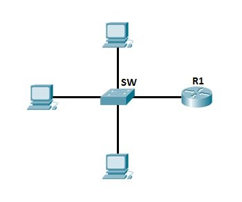
Here is an example of the typical LAN network used today:

typical switch network

NOTE – switches are sometimes called multiport bridges.

Differences between hubs and switches

To better understand the concept of packet switching based on the hardware address of a device, you need to understand how switches differ from hubs.
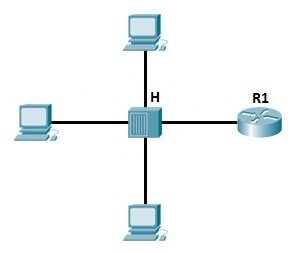
First, consider the example of a LAN, with all hosts connecting to a hub:

hub network

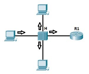
As mentioned previously, hubs create only one collision domain, so the chance for a collision to occur is high. The hub depicted above simply repeats the signal it receives out all ports, except the from which the signal was received, so no packet filtering takes place. Imagine if you had 20 hosts connected to a hub, a packet will be sent to 19 hosts, instead of just one! This can also cause security problems, because an attacker can capture all traffic on the network.

how hubs work

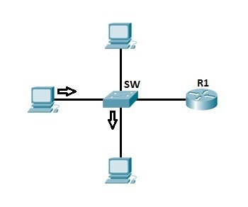
Now consider the way the switches work. We have the same topology as above, only this we are using a switch instead of a hub.

how switches work

Switches increase the number of collision domains. Each port is one collision domain, which means that the chances for collisions to occur are minimal. A switch learns which device is connected to which port and forwards a frame based on the destination MAC address included in the frame. This reduces traffic on a LAN and enhances security.

How switches work

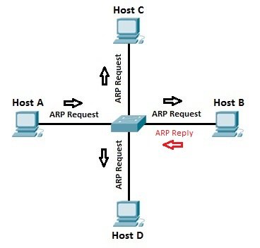
Each network card has a unique identifier called Media Access Control (MAC) address. This address is used in LANs for communication between devices on the same network segment. Devices that want to communicate need to know each other MAC address before sending out packets. They use a process called ARP (Address Resolution Protocol) to find out the MAC address of another device. When the hardware address of the destination host is known, the sending host has all the required information to communicate with the remote host.

To better understand the concept, here is an example of how a switch works.

arp process

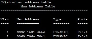
Let’s say that host A wants to communicate with host B for the first time. Host A knows the IP address of host B, but since this is the first time the two hosts communicate, hardware (MAC) addresses are not known. Host A uses an ARP process to find out the MAC address of host B. Switch forwards the ARP request out all ports except the port the host A is connected to. Host B receives the ARP request and responds with its MAC address. Host B also learns the MAC address of host A ( because host A sends its MAC address in the ARP request). The switch learns which MAC addresses are associated with which port. For example, because host B responded with the ARP request that included its MAC address, the switch knows the MAC address of host B and stores that address in its MAC address table. The same is with host A, the switch knows the MAC address of  the host A because of the ARP request. Now, when host A sends a packet to host B, the switch looks up in its MAC address table and forwards the frame only out Fa0/1 port, the port on which host B is connected.

You can display the MAC address table of the switch by using the show mac-address-table command:

show mac address table