Find Devices that connected to network In Ubuntu

Find Devices that connected to network In Ubuntu

Find Devices that connected to network In Ubuntu

We will use terminal for finding out what devices are connected to your network in Linux. The process is very simple and easy to use even for beginners. Here we go:

Get nmap:

nmap is one of the most popular network scanning tool in Linux. Use the following command to install nmap in Ubuntu:

sudo apt-get install nmap

Get IP range of the network:

Now we need to know the IP address range of the network. Use the ifconfig command to find it out. Look for wlan0 if you are using wifi or eth0 if you are using Ethernet.

user@user-notebook:~$ ifconfig

wlan0 Link encap:Ethernet HWaddr 70:f1:a1:c2:f2:e9
inet addr:192.168.1.91 Bcast:192.168.1.255 Mask:255.255.255.0
inet6 addr: fe80::73f1:a1ef:fec2:f2e8/64 Scope:Link
UP BROADCAST RUNNING MULTICAST MTU:1500 Metric:1
RX packets:2135051 errors:0 dropped:0 overruns:0 frame:0
TX packets:2013773 errors:0 dropped:0 overruns:0 carrier:0
collisions:0 txqueuelen:1000
RX bytes:1434994913 (1.4 GB) TX bytes:636207445 (636.2 MB)

The important things are highlighted in bold. As you see my IP is 192.168.1.91 and the subnet mask is 255.255.255.0 which means that the ip address range on my network varies from 192.168.1.0 to 192.168.1.255.

Scan the network:

It is advisable to use root privileges while scanning the network for more accurate information. Use the nmap command in following way:

user@user-notebook:~$ sudo nmap -sP 192.168.1.0/24
Starting Nmap 5.21 ( http://nmap.org ) at 2012-09-01 21:59 CEST

Nmap scan report for neufbox (192.168.1.1)
Host is up (0.012s latency).
MAC Address: E0:A1:D5:72:5A:5C (Unknown)
Nmap scan report for takshak-bambi (192.168.1.91)
Host is up.
Nmap scan report for android-95b23f67te05e1c8 (192.168.1.93)
Host is up (0.36s latency).

Hierarchical Network Model

Hierarchical Network Model

hierarchical network model

this source from: http://www.omnisecu.com/cisco-certified-network-associate-ccna/three-tier-hierarchical-network-model.php

Cisco suggests a Three−Tier (Three Layer) hierarchical network model, that consists of three layers: the Core layer, the Distribution layer, and the Access layer. Cisco Three-Layer network model is the preferred approach to network design.

Cisco Three-tier Network Hierarchy

The above picture can further explained based on below picture.

Cisco Three Layer Network Model

Core Layer

Core Layer consists of biggest, fastest, and most expensive routers with the highest model numbers and Core Layer is considered as the back bone of networks. Core Layer routers are used to merge geographically separated networks. The Core Layer routers move information on the network as fast as possible. The switches operating at core layer switches packets as fast as possible.

Distribution layer:

The Distribution Layer is located between the access and core layers. The purpose of this layer is to provide boundary definition by implementing access lists and other filters. Therefore the Distribution Layer defines policy for the network. Distribution Layer include high-end layer 3 switches. Distribution Layer ensures that packets are properly routed between subnets and VLANs in your enterprise.

Access layer

Access layer includes acces switches which are connected to the end devices (Computers, Printers, Servers etc). Access layer switches ensures that packets are delivered to the end devices.

Benefits of Cisco Three-Layer hierarchical model

The main benefits of Cisco Three-Layer hierarchical model is that it helps to design, deploy and maintain a scalable, trustworthy, cost effective hierarchical internetwork.

Better Performance: Cisco Three Layer Network Model allows in creating high performance networks

Better management & troubleshooting: Cisco Three Layer Network Model allows better network management and isolate causes of network trouble.

Better Filter/Policy creation and application: Cisco Three Layer Network Model allows better filter/policy creation application.

Better Scalability: Cisco Three Layer Network Model allows us to efficiently accomodate future growth.

Better Redundancy: Cisco Three Layer Network Model provides better redundancy. Multiple links across multiple devices provides better redundancy. If one switch is down, we have another alternate path to reach the destination.


another source : http://www.ciscopress.com/articles/article.asp?p=2202410&seqNum=4


Hierarchical Network Design Overview (1.1)

The Cisco hierarchical (three-layer) internetworking model is an industry wide adopted model for designing a reliable, scalable, and cost-efficient internetwork. In this section, you will learn about the access, distribution, and core layers and their role in the hierarchical network model.

Enterprise Network Campus Design (1.1.1)

An understanding of network scale and knowledge of good structured engineering principles is recommended when discussing network campus design.

Network Requirements (1.1.1.1)

When discussing network design, it is useful to categorize networks based on the number of devices serviced:

  • Small network: Provides services for up to 200 devices.
  • Medium-size network: Provides services for 200 to 1,000 devices.
  • Large network: Provides services for 1,000+ devices.

Network designs vary depending on the size and requirements of the organizations. For example, the networking infrastructure needs of a small organization with fewer devices will be less complex than the infrastructure of a large organization with a significant number of devices and connections.

There are many variables to consider when designing a network. For instance, consider the example in Figure 1-1. The sample high-level topology diagram is for a large enterprise network that consists of a main campus site connecting small, medium, and large sites.

Figure 1-1Figure 1-1 Large Enterprise Network Design

Network design is an expanding area and requires a great deal of knowledge and experience. The intent of this section is to introduce commonly accepted network design concepts.

NOTE

The Cisco Certified Design Associate (CCDA®) is an industry-recognized certification for network design engineers, technicians, and support engineers who demonstrate the skills required to design basic campus, data center, security, voice, and wireless networks.

Structured Engineering Principles (1.1.1.2)

Regardless of network size or requirements, a critical factor for the successful implementation of any network design is to follow good structured engineering principles. These principles include

  • Hierarchy: A hierarchical network model is a useful high-level tool for designing a reliable network infrastructure. It breaks the complex problem of network design into smaller and more manageable areas.
  • Modularity: By separating the various functions that exist on a network into modules, the network is easier to design. Cisco has identified several modules, including the enterprise campus, services block, data center, and Internet edge.
  • Resiliency: The network must remain available for use under both normal and abnormal conditions. Normal conditions include normal or expected traffic flows and traffic patterns, as well as scheduled events such as maintenance windows. Abnormal conditions include hardware or software failures, extreme traffic loads, unusual traffic patterns, denial-of-service (DoS) events, whether intentional or unintentional, and other unplanned events.
  • Flexibility: The ability to modify portions of the network, add new services, or increase capacity without going through a major forklift upgrade (i.e., replacing major hardware devices).

To meet these fundamental design goals, a network must be built on a hierarchical network architecture that allows for both flexibility and growth.

Hierarchical Network Design (1.1.2)

This topic discusses the three functional layers of the hierarchical network model: the access, distribution, and core layers.

Network Hierarchy (1.1.2.1)

Early networks were deployed in a flat topology as shown in Figure 1-2.

Figure 1-2Figure 1-2 Flat Switched Network

Hubs and switches were added as more devices needed to be connected. A flat network design provided little opportunity to control broadcasts or to filter undesirable traffic. As more devices and applications were added to a flat network, response times degraded, making the network unusable.

A better network design approach was needed. For this reason, organizations now use a hierarchical network design as shown in Figure 1-3.

Figure 1-3Figure 1-3 Hierarchical Network

A hierarchical network design involves dividing the network into discrete layers. Each layer, or tier, in the hierarchy provides specific functions that define its role within the overall network. This helps the network designer and architect to optimize and select the right network hardware, software, and features to perform specific roles for that network layer. Hierarchical models apply to both LAN and WAN design.

The benefit of dividing a flat network into smaller, more manageable blocks is that local traffic remains local. Only traffic that is destined for other networks is moved to a higher layer. For example, in Figure 1-3 the flat network has now been divided into three separate broadcast domains.

A typical enterprise hierarchical LAN campus network design includes the following three layers:

  • Access layer: Provides workgroup/user access to the network
  • Distribution layer: Provides policy-based connectivity and controls the boundary between the access and core layers
  • Core layer: Provides fast transport between distribution switches within the enterprise campus

Another sample three-layer hierarchical network design is displayed in Figure 1-4. Notice that each building is using the same hierarchical network model that includes the access, distribution, and core layers.

Figure 1-4Figure 1-4 Multi Building Enterprise Network Design

NOTE

There are no absolute rules for the way a campus network is physically built. While it is true that many campus networks are constructed using three physical tiers of switches, this is not a strict requirement. In a smaller campus, the network might have two tiers of switches in which the core and distribution elements are combined in one physical switch. This is referred to as a collapsed core design.

The Access Layer (1.1.2.2)

In a LAN environment, the access layer highlighted grants end devices access to the network. In the WAN environment, it may provide teleworkers or remote sites access to the corporate network across WAN connections.

As shown in Figure 1-5, the access layer for a small business network generally incorporates Layer 2 switches and access points providing connectivity between workstations and servers.

Figure 1-5Figure 1-5 Access Layer

The access layer serves a number of functions, including

  • Layer 2 switching
  • High availability
  • Port security
  • QoS classification and marking and trust boundaries
  • Address Resolution Protocol (ARP) inspection
  • Virtual access control lists (VACLs)
  • Spanning tree
  • Power over Ethernet (PoE) and auxiliary VLANs for VoIP

The Distribution Layer (1.1.2.3)

The distribution layer aggregates the data received from the access layer switches before it is transmitted to the core layer for routing to its final destination. In Figure 1-6, the distribution layer is the boundary between the Layer 2 domains and the Layer 3 routed network.

Figure 1-6Figure 1-6 Distribution Layer

The distribution layer device is the focal point in the wiring closets. Either a router or a multilayer switch is used to segment workgroups and isolate network problems in a campus environment.

A distribution layer switch may provide upstream services for many access layer switches.

The distribution layer can provide

  • Aggregation of LAN or WAN links.
  • Policy-based security in the form of access control lists (ACLs) and filtering.
  • Routing services between LANs and VLANs and between routing domains (e.g., EIGRP to OSPF).
  • Redundancy and load balancing.
  • A boundary for route aggregation and summarization configured on interfaces toward the core layer.
  • Broadcast domain control, because routers or multilayer switches do not forward broadcasts. The device acts as the demarcation point between broadcast domains.

The Core Layer (1.1.2.4)

The core layer is also referred to as the network backbone. The core layer consists of high-speed network devices such as the Cisco Catalyst 6500 or 6800. These are designed to switch packets as fast as possible and interconnect multiple campus components, such as distribution modules, service modules, the data center, and the WAN edge.

As shown in Figure 1-7, the core layer is critical for interconnectivity between distribution layer devices (for example, interconnecting the distribution block to the WAN and Internet edge).

Figure 1-7Figure 1-7 Core Layer

The core should be highly available and redundant. The core aggregates the traffic from all the distribution layer devices, so it must be capable of forwarding large amounts of data quickly.

Considerations at the core layer include

  • Providing high-speed switching (i.e., fast transport)
  • Providing reliability and fault tolerance
  • Scaling by using faster, and not more, equipment
  • Avoiding CPU-intensive packet manipulation caused by security, inspection, quality of service (QoS) classification, or other processes

Two-Tier Collapsed Core Design (1.1.2.5)

The three-tier hierarchical design maximizes performance, network availability, and the ability to scale the network design.

However, many small enterprise networks do not grow significantly larger over time. Therefore, a two-tier hierarchical design where the core and distribution layers are collapsed into one layer is often more practical. A “collapsed core” is when the distribution layer and core layer functions are implemented by a single device. The primary motivation for the collapsed core design is reducing network cost, while maintaining most of the benefits of the three-tier hierarchical model.

The example in Figure 1-8 has collapsed the distribution layer and core layer functionality into multilayer switch devices.

Figure 1-8Figure 1-8 Two-Tier Hierarchical Design

The hierarchical network model provides a modular framework that allows flexibility in network design and facilitates ease of implementation and troubleshooting.

Activity 1.1.2.6: Identify Hierarchical Network Characteristics


Exploring Your Home Computer Network with Kali Linux

Exploring Your Home Computer Network with Kali Linux

Exploring Your Home Computer Network with Kali Linux

Exploring Your Home Computer Network with Kali Linux

This article is part two in our tutorial series on how to set up a home hacking and security testing lab. If you followed along in part one, installing a Kali Linux virtual machine in VirtualBox, you have installed VirtualBox on the primary computer for your home lab and created a Kali Linux virtual guest on this host machine. The Kali system has been fully updated and VirtualBox Guest Additions have been installed on it. Finally, your Kali VM has a single network adapter running in bridged mode and you have set up an administrator account on the Kali instance.

Creating and configuring the virtual network setup outlined in the introduction, which we will do in part three of this series, requires a few more steps: we still have to download and install Metasploitable, set up the virtual network, etc. But if you’re like me, you’re probably already itching to start playing with all the toys Kali has to offer, if you haven’t already!

Home Network Analysis 101
This article will show how some of the tools that come bundled in Kali can be used to explore your existing home computer network, and test whether you can successfully identify all the devices that are connected to it. In particular, we’ll take a look at a set of tools that come bundled in Kali that can be used for network analysis: nmap/Zenmap and dumpcap/Wireshark.

These will come in handy in our eventual testing lab, but they can obviously also be used to explore your home local area network as well. Nmap is a command line network scanner, and Zenmap is a graphical interface to nmap. Dumpcap is a command line network traffic monitor, and Wireshark provides a powerful and versatile graphical interface to monitor network traffic and analyze network packet capture files.

Here’s a simple experiment. Do you happen to know how many devices are currently connected to your home network? Can you identify all of them off the top of your head? Try to do so, and make a list of them. At the very least, we know there will be at least three: the Kali guest, the host machine you are running Kali on, and your router. There may also be more computers or cell phones connected to it, and maybe even your television, refrigerator or coffee maker!

We are first going to use nmap to see if we can identify any such devices on the network, and perhaps detect one or two that we did not think or know were connected to it. We’ll then configure Wireshark and run a packet captures to get a sense for the normal traffic on the network, and then run another capture to analyze just how an nmap network scan works.

Determining Your IP Address
Before we can scan the network with nmap, we need to identify the ip address range we would like to examine. There are a number of different ways to determine your ip address on a Linux distribution such as Kali. You could use, for example, the ip or ifconfig commands in a terminal: ip addr, or sudo ifconfig.

(Note that if you are using an administrator account inside Kali, which is considered a best practice, when a non-root user enters a command such as ifconfig into a terminal, the shell will likely respond by complaining “command not found”. In Kali, sensitive system commands like ifconfig have to be run as root. To access it from your administrator account, all you need to do is add “sudo” to the front of the command: sudo ifconfig.)

These commands will provide you will a wealth of information about your network interfaces. Identify the interface that is connected to the LAN (likely eth0), and make a note of the ip address indicated after “inet” for the ip addr command, or after “int addr:” for the ifconfig command. That is your ip address on your local area network. Here are a couple ifconfig and ip addr outputs posted by the Ubuntu Journeyman:

As you can see here, the ip address for this machine is 192.168.1.4.5. Yours is likely something similar to this: for example, 192.168.1.123 or 10.0.0.56 etc. Notice in the ip addr output above, the ip address is: 192.168.4.5/24.  That means 192.168.4.5 is the ip address of that specific machine, while the /24 at the end indicates the address space for the LAN’s subnet, which in this case are all the addresses from 192.168.4.1 to 192.168.4.255.

If we were to scan this local area network with nmap, we would want to scope out all the addresses in the network’s range, which means 192.168.4.1, 192.168.4.2, 192.168.4.3, 192.168.4.4, and so on, all the way to 192.168.4.255. One shorthand way of notating this is: 192.168.4.1-255. Another common shorthand is 192.168.4.0/24.  Of course, if your address were 10.0.0.121, then the shorthand would be: 10.0.0.1-255 or 10.0.0.0/24.

Host Discovery
Let’s assume your Kali VM has the ip address 192.168.1.5 on a subnet with possible host addresses from 192.168.1.1 to 192.168.1.255. Now that we know Kali’s ip address and the address range we want to take a look at, open up a terminal and type: nmap. This will provide you with a long list of all the options available within the nmap program. Nmap is a powerful program and there are a lot of options! Perhaps the simplest possible network scan that can be conducted with nmap is a ping scan, for which we use the -sn option.

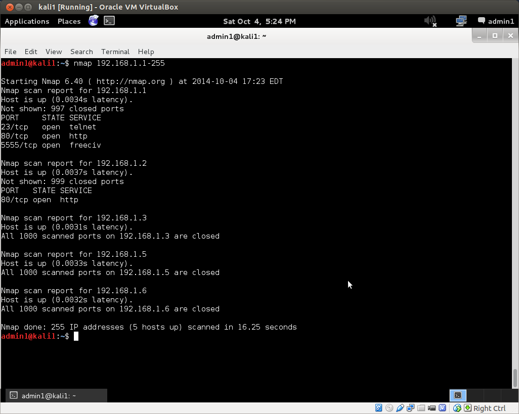
Now type nmap -sn 192.168.1.1-255 into your terminal and hit enter. (Don’t forget to substitute the address range for your network if it is different from this!) This scan will tell you how many hosts nmap discovered by sending a ping echo request to each of the addresses in the range x.x.x.1-255, and provide you with a list of the ip addresses of the hosts that returned a ping reply. This is host discovery 101. Here is the ping scan output from nmap on a simple local area network I set up for the purpose:

The ping scan found 5 hosts up with the addresses: 192.168.1.1, .2, .3, .5 and .6.  Note that in the wild, this method of discovery may not work, as it is becoming increasingly common for administrators to configure their systems so that they do not reply to simple ping echo requests, leaving a would-be ping scanner none-the-wiser about their existence.

Did your scan find the same number of hosts that you had presumed were on your network? Were there more or less?

We can use the default nmap scan to further investigate known hosts and any potential ghost hosts the ping scan may or may not have uncovered. For this, simply remove the -sn option from the command above: nmap 192.168.1-255. Here’s the output of the default nmap scan on the same network as above:

Nmap has returned much more information. It found three open ports on the router at 192.168.1.1, as well as an open web server port on host 192.168.1.2.  All scanned ports on the remaining hosts were closed.

You can also use nmap to further investigate known hosts. The -A option in nmap enables operating system detection and version detection. Pick out a couple of the hosts discovered by your nmap scans, for which you already know the operating system type and version. Now scan these hosts with nmap for OS and verstion detection by adding them to your host address target list, separated by commas.  For example, if I would scan the router and web server discovered above for OS and version detection with the command: nmap -A 192.168.1.1,2. This will return more information, if any is determined, on those hosts.

You can obviously also run an OS and version detection scan over the whole network with the command: nmap -A 192.168.1.1-255. Depending on the number of hosts on your network, this scan could take a couple minutes to complete. If you press <Enter> while the scan is running, it will give you an update on its progress.

If there are more and a handful of hosts on your network, the output can be hard to parse in the terminal. You could send the output to a file with:  nmap -A 192.168.1.1-255 > fileName.txt. Or you could use one of nmap’s own built-in file output options.

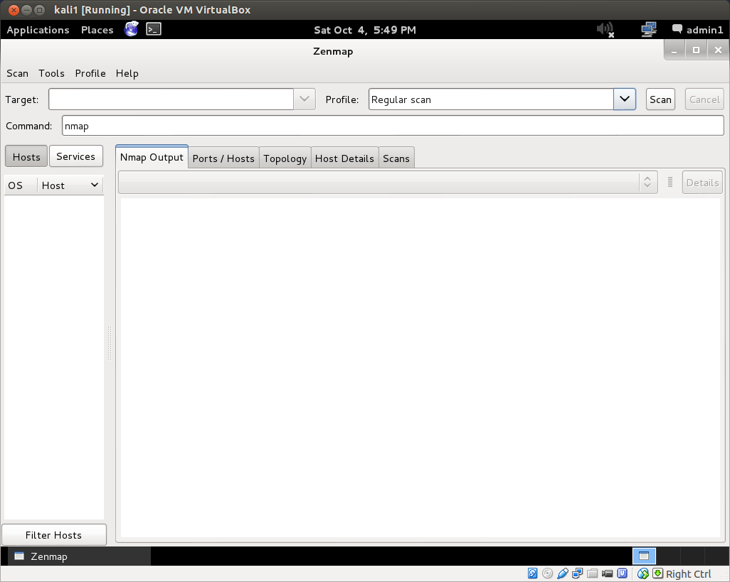
But this is also where Zenmap comes in quite handy. Open up Zenmap from Applications->Kali Linux->Information Gathering->Network Scanners. If you are running as an administrator and not root, as you should be, you will get a message stating that not all of nmap’s functionality can be accessed without root privileges. Root is not necessary for basic scans. However, you can run Zenmap as root by opening a terminal and typing: sudo zenmap. The Zenmap interface:

The Zenmap interface is pretty straightforward. Enter the target ip address or address range into the target field. Changing the scan profile from the drop down menu changes the scan command. You can also manually enter or edit commands in the command field. After you run a scan, Zenmap also helpfully breaks down the results for you, providing host details, port lists, network topology graphics and more.

Play around with the various built-in scan types. Can you identify all the hosts on your home network with a ping scan? a regular scan? an intense scan? Can you identify all the open ports on those hosts? If you have a laptop or another device that you frequently use to connect to the internet over public wi-fi hotspots, you can also do intensive scans of those devices to determine if there are any open ports that would represent a potential security vulnerability. Identifying open ports is important for vulnerability assessment, because these represent potential reconnaissance or attack vectors.

Network Traffic Capture and Analysis with Wireshark
Nmap scans a network and probes hosts by sending out ip packets to, and inspecting the replies from, its target at a given address. With 255 addresses to scan along with 1000 ports on all discovered hosts in the default scan of the subnet above, that’s a lot of network traffic! What does the packet traffic generated by a scan look like on the network?

To answer this question, we can use Wireshark and dumpcap. Dumpcap, as its name implies, is a command line tool that dumps captured network traffic. Wireshark provides a graphical user interface to analyze these sorts of dump files, which are collections of all the network traffic to which the given network interface was privy.

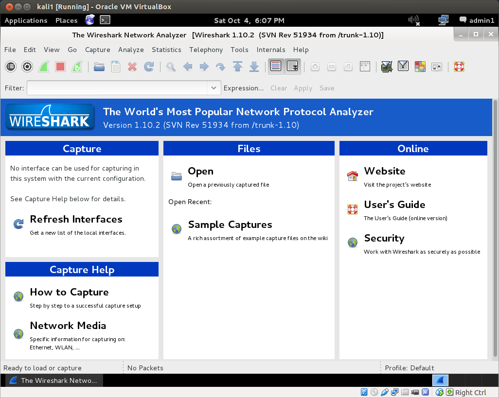
If run with the proper privileges, Wireshark can capture live network traffic as well. In Kali, you can find Wireshark under: Applications->Kali Linux->Top 10 Security Tools. Unless you have already configured Wireshark with the appropriate settings, when you open it for the first time you will be informed by the “Capture” panel that “No interface can be used for capturing in this system with the current configuration.”

In its documentation, Wireshark recommends appropriate settings to enable capture privileges. This also suggests confirming that Wireshark can also be run as root. To run Wireshark as root, you can log in as root, or run sudo wireshark in a terminal. When you run Wireshark as root, you will first be given a usage warning and provided with sources for how to set up proper privileges. This forum post on AskUbuntu boils the process down to three simple steps.

Now that you’ve enabled live captures in Wireshark, let’s run one! Click “Interface List” in the Capture panel of the default view. Choose the interface that is connected to the network (it will indicate your ip address on that network), and click Start.

This will immediately begin a live capture of all the packets on the network to which the interface has access. At the very least, it will detect: 1) packets it sends out, 2) packets it receives directly, 3) packets it receives indirectly if they are broadcast to all the hosts on the network.

If you have never viewed a network packet capture before, you may be surprised what you can see, and what information is simply being broadcast over the network. You’ll probably find messages from your router, you’ll see internet traffic packets if you are viewing a webpage in a Kali browser, or on Kali’s host computer (depending on whether or not Promiscuous Mode is enabled in the VirtualBox advanced network settings for your Kali machine). You might find that one device is especially chatty for no good reason. There might be devices pathetically sending out calls to other devices that have been removed from the network, such as a laptop searching for a printer that has been turned off, and so on.

The default Wireshark packet capture interface numbers each packet it captures, and then notes the time after the capture began that it received the packet, the ip address of the source of the packet, the ip address of the destination of the packet, the protocol, the packet’s length and some info. You can double click an individual packet to inspect it more closely.

If you ping your router (which you should have been able to identify via nmap analysis) from Kali, you’ll see all the requests and replies, obviously, since the Wireshark capture and the ping are running on the same machine. But the Kali guest shares its interface with the host machine. If you enable promiscuous mode in the advanced network settings inside VirtualBox for your Kali instance, when you ping your router from the host machine itself, the Wireshark capture will similarly allow you to see all requests and replies, they’re going over the same interface! If you disable Promiscuous Mode, on this other hand, this will not be the case. In this case, packets to and from the host computer will not be picked up, as if it were a completely separate physical machine. Similarly, if you ping your router from a different computer, you will not see the request/reply traffic at all, though perhaps you might pick up an ARP if the requester does not already know the (hardware) address of the request’s intended recipient.

After getting a feel for what the base level network traffic looks like on your network, start a new capture, and then run a simple scan from nmap or Zenmap, and watch the result in Wireshark. When the scan is finished, stop the capture and save the file. Capturing the simple nmap ping scan from above on my network resulted in a file with over 800 packets! Now you can analyze the network traffic generated by the scan itself. You’ll probably want to play around with Wireshark for a bit to get a sense of what it offers. There are tons of menus and options in Wireshark that can be tweaked and optimized for your own ends.

Well, that’s it for this article. In part three of our hack lab tutorial series, we’ll install our victim machine, an instance of Metasploitable2, in VirtualBox and set up a completely virtual lab network to explore some more tools that are bundled in Kali. As always, comments, questions, corrections and the like are welcome below.

Configuration Example Static Routes

Configuration Example Static Routes

Configuration Example Static Routes

Figure 6-1 shows the network topology for the configuration that follows, which shows how to configure static routes using the commands covered in this chapter.


Figure 6-1 Network Topology for Static Route Configuration

NOTE

The host name, password, and interfaces have all been configured as per the configuration in the Chapter 3 configuration example.

Boston Router

Boston>en  
Boston#config t  
Boston(config)#ip route 172.16.30.0 255.255.255.0 172.16.20.2 Configures a static route using the next-hop address
Boston(config)#ip route 172.16.40.0 255.255.255.0 172.16.20.2  
Boston(config)#ip route 172.16.50.0 255.255.255.0 172.16.20.2  
Boston(config)#exit  
Boston#copy run start  

Buffalo Router

Buffalo>en  
Buffalo#config t  
Buffalo(config)#ip route 172.16.10.0 255.255.255.0 s1 Configures a static route using the exit interface
Buffalo(config)#ip route 172.16.50.0 255.255.255.0 s0  
Boston(config)#exit  
Boston#copy run start  

Bangor Router

Bangor>en  
Bangor#config t  
Bangor(config)#ip route 0.0.0.0 0.0.0.0 s1 Configures a static route using the default route
Bangor(config)#exit  
Bangor#copy run start

نبذة لدخول عالم ومجال سيسكو Cisco

السلام عليكم ورحمة الله و بركاته

الكثير منا لم يكن يعرف ماهي الشبكات ؟ اذا اول سؤال يجب ان نسأله لنفسنا ماهي الشبكات

قبل ذلك اريد ان اذكر بشئ بسيط :
اخي المبتدأ ارغب ان اشرح لك معنى تقنية المعلومات IT بصوره مختصره فالشبكات جزء منها

تقنيتة المعلومات تنقسم الى قسمين

الاول / SOFTWARE , C , C++ , JAVA etc………

الثاني :

Hardware , MCSE ,MCITP,CCNA,CCNP …..etc

بمعنى اخر او بتقسيم اخر

LAN : SYSTEM ADMINISTRATOR الشبكه المحليه
الشبكه الواسعه WAN : NETWORK/ SECURITY ADMINISTRATOR

اذا اردنا العمل مع الشبكه المحليه هذا يعني اننا سنحتاج للاتي

1-اكثر من كمبيوتر واحد
2- O/S نظام تشغيل و سوف اشرح انظمة التشغيل بصوره سريعه

مايكروسوفت انتج ما يسمى بي :

ا- نظام التشغيل الخاص بالمستخدم CLIENT

و هي من الاقدم الى الاحدث

WIN 3.11
WIN 95
WIN 98
WIN 2000 PRO
WIN XP SP1,SP2,SP3
WIN VISTA
WIN 7
ب-نظام التشغيل المتحكم بالمستخدم SERVERS

و هي من الاقدم الى الاحدث

WIN SERVER NT 4.0
WIN SERVER 2000 بإصدارات ثلاثه هي
interprise, web, data center
WIN SERVER 2003 OR MCSE
WIN SERVER 2008 OR MCITP

LINUX ,SUN ايضا لا ننسى انظمة التشغيل هذه و هي ذات حمايه عاليه جدا و اغلب شركات الاتصالات تعمل بهذه الانواع من انظمة التشغيل اذا كانت الشركه معنمده على اجهزه من شركة IBM و هي شركه مصنعه للسيرفرات و غيرها .

3- و نعود مرة اخرى و نذكر ثالث احتياجاتنا لعمل شبكه محليه NIC او ما يطلق عليه كرت الشبكه فمن غيره لايوجد شبكه و البورت الذي به او المدخل يسمى ETHERNET , FAST ETHERNET , GIGA ETHERNET

4-الكيبل CABLE و سأتحدث عنها في نقاط سريعه و التفصيل انت ستبحث عنه انا اعطيك الطريقه فقط كيف و بماذا تبدأ و لماذا ؟

النوع الاول: COXIAL
النوع الثاني : TWISTED و ينقسم الى نوعين و الفرق بينهما ان الاول صلب و ينكسر بسرعه لذلك غير مستخدم
لثاني مرن و يسهل التعامل معه

الاول STP shielded twisted pair و هذا هو النوع الصلب الغير مستخدم

الثاني UTP unshielded twisted pair و ههذا النوع المرن و يتكون من 8 اسلاك , و منها نوعان احدها للهاتف cat 1 RJ 11 2mbps
cat2 4mbps
cat3 10mbps
cat 4 16mbps
cat5 و هذا يستخدم للنت و يركب بكلبس يسمى RJ45 100MBPS
cat 6 1000 mbps

النوع الثالث / الفايبر اوبتيك يعني لازم تتعرف على جميع الكيبل

اريد من الجميع التركيز هنا
5- protocols و هذا ما سنحتاج الى معرفته لان الشبكه كلها تعمل ببرتكولات

6- الاجهزه الموصله other divices : switch , hub ,

يعني لازم تتعرف على كل انواع الاجهزه المستخدمه

بعد اعداد كل هذا سنصل سنكون قد انجزنا شبكه محليه و لكن ايضا هناك شئ صغير يجب ان نعرفه

اذا كانت الشبكه مرتبطه من غير متحكم تسمى WORKGROUP

اذا كانت مرتبطه بمتحكم اي سيرفير 2008 او 2003 او غيره تسمى دومين DOMAIN و هذا النوع تعمل به الشركات حتى تتحكم في مسار عمل الشركه و الموظفين و تسهيل نقل البيانات من مكان لاخر.

نأتي هنا و للاهم المهم و الذهب و الالماس عالم سيسكو :

بكل بساطه في الاعلى ذكرت ان الشركات تعمل بدومين هذا يعني ان الشركه اصبحت تتعامل بالكمبيوتر مربوطه ببعضها البعض اي هناك شبكه و في موقع محدد مثلا الرياض

قام صاحب الشركه بإنشاء فرع اخر في احدى المدن او الدول بالتأكيد سوف يقوم بتجهيز الفرع الجديد بكمبيوترات , او فالنقل سيقوم بعمل شبكه محليه للفرع لتسهيل العمل كما في الرياض

صاحب الشركه يريد ان يربط شبكة الفرع الجديد بالشركة الرئيسيه في الرياض ماذا سيحدث او ماذا سنفعل هنا ؟

سيأتي دور سيسكو اي اننا سنتعامل مع الراوترز و السويتش من الطبقه الثانيه و سوتيش من الطبقه الثالثه و هي تعمل عمل الراوتر ايضا حديثه جدا

فأجهزة سيسكو هي التي تعمل على ربط تلك المددينتين او الدولتين ببعضهما البعض و تسمى هذه الشبكه بالشبكه الواسعه WAN

سأكتفي بهذا الان وسأكمل بقية القصه و سأدلك اخي الى طريقك نحو كيفية دراسة و تطبيق الشبكه الواسعه و اعتقد ان المنتدى به الكثير من الدرر النفيسه مثل الاستاذ عدنان و غيره من الاخوان الافاضل و هذا الطرح هو طرح مبدأي لك اخي المبتدأ حتى تعرف ماهي الشبكه الواسعه و علاقتها بالشبكه المحليه و لكي تحدد ان كنت تريد ان تصبح mcitp or cisco certified


المصدر