Feb 15, 2016 | binary, conversion, convert, decimal, hexadecimal, Learn and Teach, numbering
Number Converting
Source: http://www.robotroom.com/
Number Systems
There are infinite ways to represent a number. The four commonly associated with modern computers and digital electronics are: decimal, binary, octal, and hexadecimal.
Decimal (base 10) is the way most human beings represent numbers. Decimal is sometimes abbreviated as dec.
Decimal counting goes:
0, 1, 2, 3, 4, 5, 6, 7, 8, 9, 10, 11, 12, 13, 14, 15, 16, 17, 18, and so on.
Binary (base 2) is the natural way most digital circuits represent and manipulate numbers. (Common misspellings are “bianary”, “bienary”, or “binery”.) Binary numbers are sometimes represented by preceding the value with ‘0b’, as in 0b1011. Binary is sometimes abbreviated as bin.
Binary counting goes:
0, 1, 10, 11, 100, 101, 110, 111, 1000, 1001, 1010, 1011, 1100, 1101, 1110, 1111, 10000, 10001, and so on.
Octal (base 8) was previously a popular choice for representing digital circuit numbers in a form that is more compact than binary. Octal is sometimes abbreviated as oct.
Octal counting goes:
0, 1, 2, 3, 4, 5, 6, 7, 10, 11, 12, 13, 14, 15, 16, 17, 20, 21, and so on.
Hexadecimal (base 16) is currently the most popular choice for representing digital circuit numbers in a form that is more compact than binary. (Common misspellings are “hexdecimal”, “hexidecimal”, “hexedecimal”, or “hexodecimal”.) Hexadecimal numbers are sometimes represented by preceding the value with ‘0x’, as in 0x1B84. Hexadecimal is sometimes abbreviated as hex.
Hexadecimal counting goes:
0, 1, 2, 3, 4, 5, 6, 7, 8, 9, A, B, C, D, E, F, 10, 11, and so on.
[ad id=”13280″]
All four number systems are equally capable of representing any number. Furthermore, a number can be perfectly converted between the various number systems without any loss of numeric value.
At first blush, it seems like using any number system other than human-centric decimal is complicated and unnecessary. However, since the job of electrical and software engineers is to work with digital circuits, engineers require number systems that can best transfer information between the human world and the digital circuit world.
It turns out that the way in which a number is represented can make it easier for the engineer to perceive the meaning of the number as it applies to a digital circuit. In other words, the appropriate number system can actually make things less complicated.
Fundamental Information Element of Digital Circuits
Almost all modern digital circuits are based on two-state switches. The switches are either on or off. It doesn’t matter if the switches are actually physical switches, vacuum tubes, relays, or transistors. And, it doesn’t matter if the ‘on’ state is represented by 1.8 V on a cutting-edge CPU core, -12 V on a RS-232 interface chip, or 5 V on a classic TTL logic chip.
Because the fundamental information element of digital circuits has two states, it is most naturally represented by a number system where each individual digit has two states: binary.
For example, switches that are ‘on’ are represented by ‘1’ and switches that are ‘off’ are represented by ‘0’. It is easy to instantly comprehend the values of 8 switches represented in binary as 10001101. It is also easy to build a circuit to display each switch state in binary, by having an LED (lit or unlit) for each binary digit.
Making Values More Compact
“Binary digit” is a little unwieldy to say over and over, so the term was contracted to “bit”. Not only is the term “binary digit” a little unwieldy, but so is the length of a binary number, since each digit can only represent one switch. As digital circuits grew more complex, a more compact form of representing circuit information became necessary.
An octal number (base 8) can be up to 1/3 the length of a binary number (base 2). 8 is a whole power of 2 (23=8). That means three binary digits convert neatly into one octal digit.
A hexadecimal number (base 16) can be up to 1/4 the length of a binary number. 16 is a whole power of 2 (24=16). That means four binary digits convert neatly into one hexadecimal digit.
Unfortunately, decimal (base 10) is not a whole power of 2. So, it is not possible to simply chunk groups of binary digits to convert the raw state of a digital circuit into the human-centric format.
Let’s see how to convert a number from binary.
[incor name=”2. Binary Number Conversion”]
2. Binary Number Conversion
Binary to Octal
An easy way to convert from binary to octal is to group binary digits into sets of three, starting with the least significant (rightmost) digits.
| Binary: 11100101 = |
11 100 101 |
|
|
011 100 101 |
Pad the most significant digits with zeros if necessary to complete a group of three. |
Then, look up each group in a table:
| Binary: |
000 |
001 |
010 |
011 |
100 |
101 |
110 |
111 |
| Octal: |
0 |
1 |
2 |
3 |
4 |
5 |
6 |
7 |
| Binary = |
011 |
100 |
101 |
|
| Octal = |
3 |
4 |
5 |
= 345 oct |
Binary to Hexadecimal
An equally easy way to convert from binary to hexadecimal is to group binary digits into sets of four, starting with the least significant (rightmost) digits.
Binary: 11100101 = 1110 0101
Then, look up each group in a table:
| Binary: |
0000 |
0001 |
0010 |
0011 |
0100 |
0101 |
0110 |
0111 |
| Hexadecimal: |
0 |
1 |
2 |
3 |
4 |
5 |
6 |
7 |
| Binary: |
1000 |
1001 |
1010 |
1011 |
1100 |
1101 |
1110 |
1111 |
| Hexadecimal: |
8 |
9 |
A |
B |
C |
D |
E |
F |
| Binary = |
1110 |
0101 |
|
| Hexadecimal = |
E |
5 |
= E5 hex |
[ad id=”13280″]
Binary to Decimal
They say there are only 10 people in this world: those that understand binary and those that don’t. Ha ha.
If you don’t get that joke, you’ll need a method to convert from binary to decimal. One method involves addition and multiplication.
- Start the decimal result at 0.
- Remove the most significant binary digit (leftmost) and add it to the result.
- If all binary digits have been removed, you’re done. Stop.
- Otherwise, multiply the result by 2.
- Go to step 2.
[ad id=”13280″]
Here is an example of converting 11100000000 binary to decimal:
| Binary Digits |
Operation |
Decimal Result |
Operation |
Decimal Result |
| 11100000000 |
+1 |
1 |
× 2 |
2 |
| 1100000000 |
+1 |
3 |
× 2 |
6 |
| 100000000 |
+1 |
7 |
× 2 |
14 |
| 00000000 |
+0 |
14 |
× 2 |
28 |
| 0000000 |
+0 |
28 |
× 2 |
56 |
| 000000 |
+0 |
56 |
× 2 |
112 |
| 00000 |
+0 |
112 |
× 2 |
224 |
| 0000 |
+0 |
224 |
× 2 |
448 |
| 000 |
+0 |
448 |
× 2 |
896 |
| 00 |
+0 |
896 |
× 2 |
1792 |
| 0 |
+0 |
1792 |
done. |
|
Let’s try converting from decimal
3. Decimal Number Conversion
A repeated division and remainder algorithm can convert decimal to binary, octal, or hexadecimal.
- Divide the decimal number by the desired target radix (2, 8, or 16).
- Append the remainder as the next most significant digit.
- Repeat until the decimal number has reached zero.
Decimal to Binary
Here is an example of using repeated division to convert 1792 decimal to binary:
| Decimal Number |
Operation |
Quotient |
Remainder |
Binary Result |
| 1792 |
÷ 2 = |
896 |
0 |
0 |
| 896 |
÷ 2 = |
448 |
0 |
00 |
| 448 |
÷ 2 = |
224 |
0 |
000 |
| 224 |
÷ 2 = |
112 |
0 |
0000 |
| 112 |
÷ 2 = |
56 |
0 |
00000 |
| 56 |
÷ 2 = |
28 |
0 |
000000 |
| 28 |
÷ 2 = |
14 |
0 |
0000000 |
| 14 |
÷ 2 = |
7 |
0 |
00000000 |
| 7 |
÷ 2 = |
3 |
1 |
100000000 |
| 3 |
÷ 2 = |
1 |
1 |
1100000000 |
| 1 |
÷ 2 = |
0 |
1 |
11100000000 |
| 0 |
done. |
|
|
|
|
Decimal to Octal
Here is an example of using repeated division to convert 1792 decimal to octal:
| Decimal Number |
Operation |
Quotient |
Remainder |
Octal Result |
| 1792 |
÷ 8 = |
224 |
0 |
0 |
| 224 |
÷ 8 = |
28 |
0 |
00 |
| 28 |
÷ 8 = |
3 |
4 |
400 |
| 3 |
÷ 8 = |
0 |
3 |
3400 |
| 0 |
done. |
|
|
|
|
Decimal to Hexadecimal
Here is an example of using repeated division to convert 1792 decimal to hexadecimal:
| Decimal Number |
Operation |
Quotient |
Remainder |
Hexadecimal Result |
| 1792 |
÷ 16 = |
112 |
0 |
0 |
| 112 |
÷ 16 = |
7 |
0 |
00 |
| 7 |
÷ 16 = |
0 |
7 |
700 |
| 0 |
done. |
|
|
|
|
The only addition to the algorithm when converting from decimal to hexadecimal is that a table must be used to obtain the hexadecimal digit if the remainder is greater than decimal 9.
| Decimal: |
0 |
1 |
2 |
3 |
4 |
5 |
6 |
7 |
| Hexadecimal: |
0 |
1 |
2 |
3 |
4 |
5 |
6 |
7 |
| Decimal: |
8 |
9 |
10 |
11 |
12 |
13 |
14 |
15 |
| Hexadecimal: |
8 |
9 |
A |
B |
C |
D |
E |
F |
[ad id=”13279″]
The addition of letters can make for funny hexadecimal values. For example, 48879 decimal converted to hex is:
| Decimal Number |
Operation |
Quotient |
Remainder |
Hexadecimal Result |
| 48879 |
÷ 16 = |
3054 |
15 |
F |
| 3054 |
÷ 16 = |
190 |
14 |
EF |
| 190 |
÷ 16 = |
11 |
14 |
EEF |
| 11 |
÷ 16 = |
0 |
11 |
BEEF |
| 0 |
done. |
|
|
|
|
Other fun hexadecimal numbers include: AD, BE, FAD, FADE, ADD, BED, BEE, BEAD, DEAF, FEE, ODD, BOD, DEAD, DEED, BABE, CAFE, C0FFEE, FED, FEED, FACE, BAD, F00D, and my initials DAC.
Now on to octal conversions…
4. Octal Number Conversion
Octal to Binary
Converting from octal to binary is as easy as converting from binary to octal. Simply look up each octal digit to obtain the equivalent group of three binary digits.
| Octal: |
0 |
1 |
2 |
3 |
4 |
5 |
6 |
7 |
| Binary: |
000 |
001 |
010 |
011 |
100 |
101 |
110 |
111 |
| Octal = |
3 |
4 |
5 |
|
| Binary = |
011 |
100 |
101 |
= 011100101 binary |
Octal to Hexadecimal
When converting from octal to hexadecimal, it is often easier to first convert the octal number into binary and then from binary into hexadecimal. For example, to convert 345 octal into hex:
(from the previous example)
| Octal = |
3 |
4 |
5 |
|
| Binary = |
011 |
100 |
101 |
= 011100101 binary |
Drop any leading zeros or pad with leading zeros to get groups of four binary digits (bits):
Binary 011100101 = 1110 0101
Then, look up the groups in a table to convert to hexadecimal digits.
| Binary: |
0000 |
0001 |
0010 |
0011 |
0100 |
0101 |
0110 |
0111 |
| Hexadecimal: |
0 |
1 |
2 |
3 |
4 |
5 |
6 |
7 |
| Binary: |
1000 |
1001 |
1010 |
1011 |
1100 |
1101 |
1110 |
1111 |
| Hexadecimal: |
8 |
9 |
A |
B |
C |
D |
E |
F |
| Binary = |
1110 |
0101 |
|
| Hexadecimal = |
E |
5 |
= E5 hex |
Therefore, through a two-step conversion process, octal 345 equals binary 011100101 equals hexadecimal E5.
[ad id=”13280″]
Octal to Decimal
Converting octal to decimal can be done with repeated division.
- Start the decimal result at 0.
- Remove the most significant octal digit (leftmost) and add it to the result.
- If all octal digits have been removed, you’re done. Stop.
- Otherwise, multiply the result by 8.
- Go to step 2.
| Octal Digits |
Operation |
Decimal Result |
Operation |
Decimal Result |
| 345 |
+3 |
3 |
× 8 |
24 |
| 45 |
+4 |
28 |
× 8 |
224 |
| 5 |
+5 |
229 |
done. |
|
The conversion can also be performed in the conventional mathematical way, by showing each digit place as an increasing power of 8.
345 octal = (3 * 82) + (4 * 81) + (5 * 80) = (3 * 64) + (4 * 8) + (5 * 1) = 229 decimal
Converting from hexadecimal is next…
5. Hexadecimal Number Conversion
Hexadecimal to Binary
Converting from hexadecimal to binary is as easy as converting from binary to hexadecimal. Simply look up each hexadecimal digit to obtain the equivalent group of four binary digits.
| Hexadecimal: |
0 |
1 |
2 |
3 |
4 |
5 |
6 |
7 |
| Binary: |
0000 |
0001 |
0010 |
0011 |
0100 |
0101 |
0110 |
0111 |
| Hexadecimal: |
8 |
9 |
A |
B |
C |
D |
E |
F |
| Binary: |
1000 |
1001 |
1010 |
1011 |
1100 |
1101 |
1110 |
1111 |
| Hexadecimal = |
A |
2 |
D |
E |
|
| Binary = |
1010 |
0010 |
1101 |
1110 |
= 1010001011011110 binary |
Hexadecimal to Octal
When converting from hexadecimal to octal, it is often easier to first convert the hexadecimal number into binary and then from binary into octal. For example, to convert A2DE hex into octal:
(from the previous example)
| Hexadecimal = |
A |
2 |
D |
E |
|
| Binary = |
1010 |
0010 |
1101 |
1110 |
= 1010001011011110 binary |
Add leading zeros or remove leading zeros to group into sets of three binary digits.
Binary: 1010001011011110 = 001 010 001 011 011 110
Then, look up each group in a table:
| Binary: |
000 |
001 |
010 |
011 |
100 |
101 |
110 |
111 |
| Octal: |
0 |
1 |
2 |
3 |
4 |
5 |
6 |
7 |
| Binary = |
001 |
010 |
001 |
011 |
011 |
110 |
|
| Octal = |
1 |
2 |
1 |
3 |
3 |
6 |
= 121336 octal |
Therefore, through a two-step conversion process, hexadecimal A2DE equals binary 1010001011011110 equals octal 121336.
[ad id=”13279″]
Hexadecimal to Decimal
Converting hexadecimal to decimal can be performed in the conventional mathematical way, by showing each digit place as an increasing power of 16. Of course, hexadecimal letter values need to be converted to decimal values before performing the math.
| Hexadecimal: |
0 |
1 |
2 |
3 |
4 |
5 |
6 |
7 |
| Decimal: |
0 |
1 |
2 |
3 |
4 |
5 |
6 |
7 |
| Hexadecimal: |
8 |
9 |
A |
B |
C |
D |
E |
F |
| Decimal: |
8 |
9 |
10 |
11 |
12 |
13 |
14 |
15 |
A2DE hexadecimal:
= ((A) * 163) + (2 * 162) + ((D) * 161) + ((E) * 160)
= (10 * 163) + (2 * 162) + (13 * 161) + (14 * 160)
= (10 * 4096) + (2 * 256) + (13 * 16) + (14 * 1)
= 40960 + 512 + 208 + 14
= 41694 decimal
Finally, why you might choose one number system over another…
6. Selecting a Numbering System
The appropriate numbering system to represent a value depends on the application. There are advantages and disadvantages to each numbering system.
When interfacing with non-engineers, decimal remains the numbering system of choice. For example, I’d have heart attack if the IRS told me that I owed them 1000000 dollars, when they actually meant to say 64 decimal.
Modern computers have lots of memory and disk space for programs. However, many low-end microcontrollers can be quite tight on space. Outputting a decimal value to a serial port or display requires the number be divided by 10 to break off each digit. Depending on the capabilities of the microcontroller, the divide-by-ten routine alone can take up more room than an entire hexadecimal output routine!
[ad id=”13280″]
When diagnosing an output pin logic problem, it isn’t immediately helpful to see that the microcontroller’s port B is set to 180 decimal. I’d prefer to see the pins as 10110100 binary. The same thing is true when looking at bit flags in memory. A disadvantage of binary is that it gets lengthy fairly quickly.
When debugging dumps of memory, disks, or data streams on modern microcontroller and computers, hexadecimal provides a compact format that is easy to break into bytes and convert into bits. In my software career, I routine examine lengthy log files detailing all the bytes sent over the air on the wireless networks.
Octal has fallen out of usage over the last thirty years due to microprocessors and microcontrollers processing data in bit chunks that are not evenly divisible by 3 (4-bit, 8-bit, 16-bit, 32-bit, 64-bit) . Octal does have the advantage of requiring only number symbols (0-8), as opposed to hexadecimal (0-9, A-F). So, octal still finds some limited usage on numeric-only displays.
To summarize, I switch between using binary, decimal, and hexadecimal on a regular basis, depending which format most clearly expresses the data that the number represents.
Feb 11, 2016 | ccna, exam, Learn and Teach, Networking, OSPF, OSPF Questions 2, questions, Quiz, test
Question 1
Into which two types of areas would an area border router (ABR) inject a default route? (Choose two)
A. the autonomous system of a different interior gateway protocol (IGP)
B. area 0
C. totally stubby
D. NSSA
E. stub
F. the autonomous system of an exterior gateway protocol (EGP)
Answer: C E
Explanation
Both stub area & totally stubby area allow an ABR to inject a default route. The main difference between these 2 types of areas is:
+ Stub area replaces LSA Type 5 (External LSA – created by an ASBR to advertise network from another autonomous system) with a default route
+ Totally stubby area replaces both LSA Type 5 and LSA Type 3 (Summary LSA – created by an ABR to advertise network from other areas, but still within the AS, sometimes called interarea routes) with a default route.
Below summarizes the LSA Types allowed and not allowed in area types:
| Area Type |
Type 1 & 2 (within area) |
Type 3 (from other areas) |
Type 4 |
Type 5 |
Type 7 |
| Standard & backbone |
Yes |
Yes |
Yes |
Yes |
No |
| Stub |
Yes |
Yes |
No |
No |
No |
| Totally stubby |
Yes |
No |
No |
No |
No |
| NSSA |
Yes |
Yes |
No |
No |
Yes |
| Totally stubby NSSA |
Yes |
No |
No |
No |
Yes |
Question 2
Which three restrictions apply to OSPF stub areas? (Choose three)
A. No virtual links are allowed.
B. The area cannot be a backbone area.
C. Redistribution is not allowed unless the packet is changed to a type 7 packet.
D. The area has no more than 10 routers.
E. No autonomous system border routers are allowed.
F. Interarea routes are suppressed.
Answer: A B E
Question 3
Refer to the partial configurations in the exhibit. What address is utilized for DR and BDR identification on Router1?
| Router1#show run**** output omitted ******
interface serial1/1
ipv6 address 2001:410:FFFE:1::64/64
ipv6 ospf 100 area 0
!
interface serial2/0
ipv6 address 3FFF:B00:FFFF:1::2/64
ipv6 ospf 100 area 0
!
ipv6 router ospf
router-id 10.1.1.3 |
A. the serial 1/1 address
B. the serial 2/0 address
C. a randomly generated internal address
D. the configured router-id address
Answer: D
Explanation
In OSPFv3 and OSPF version 2, the router uses the 32-bit IPv4 address to select the router ID for an OSPF process. The router ID selection process for OSPFv3 is described below (same as OSPF version 2):
1. The router ID is used if explicitly configured with the router-id command.
2. Otherwise, the highest IPv4 loopback address is used.
3. Otherwise, the highest active IPv4 address.
4. Otherwise, the router ID must be explicitly configured.
In this case the router ID 10.1.1.3 is explicitly configured -> D is correct.
Question 4
By default, which statement is correct regarding the redistribution of routes from other routing protocols into OSPF?
A. They will appear in the OSPF routing table as type E1 routes.
B. They will appear in the OSPF routing table as type E2 routes.
C. Summarized routes are not accepted.
D. All imported routes will be automatically summarized when possible.
E. Only routes with lower administrative distances will be imported.
Answer: B
Explanation
Type E1 external routes calculate the cost by adding the external cost to the internal cost of each link that the packet crosses while the external cost of E2 packet routes is always the external cost only. E2 is useful if you do not want internal routing to determine the path. E1 is useful when internal routing should be included in path selection. E2 is the default external metric when redistributing routes from other routing protocols into OSPF -> B is correct.
Question 5
Which statement is true about OSPF Network LSAs?
A. They are originated by every router in the OSPF network. They include all routers on the link, interfaces, the cost of the link, and any known neighbor on the link.
B. They are originated by the DR on every multi-access network. They include all attached routers including the DR itself.
C. They are originated by Area Border Routers and are sent into a single area to advertise destinations outside that area.
D. They are originated by Area Border Router and are sent into a single area to advertise an Autonomous System Border Router.
Answer: B
Explanation
Popular LSA Types are listed below:
| LSA Type |
Description |
Details |
| 1 |
Router LSA |
Generated by all routers in an area to describe their directly attached links |
| 2 |
Network LSA |
Advertised by the DR of the broadcast network (does not cross ABR) |
| 3 |
Summary LSA |
Advertised by the ABR of originating area |
| 4 |
Summary LSA |
Generated by the ABR of the originating area to advertise an ASBR to all other areas in the autonomous system |
| 5 |
AS external LSA |
Used by the ASBR to advertise networks from other autonomous systems |
| 7 |
Defined for NSSAs |
Generated by an ASBR inside a Not-so-stubby area (NSSA) to describe routes redistributed into the NSSA |
Question 6
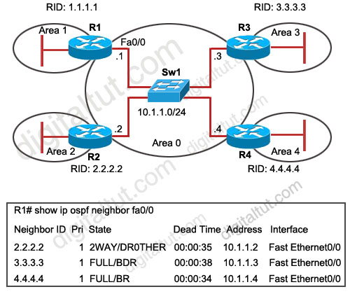
Refer to the exhibit. OSPF is configured on all routers in the network. On the basis of the show ip ospf neighbor output, what prevents R1 from establishing a full adjacency with R2?

A. Router R1 will only establish full adjacency with the DR and BDR on broadcast multiaccess networks.
B. Router R2 has been elected as a DR for the broadcast multiaccess network in OSPF area
C. Routers R1 and R2 are configured as stub routers for OSPF area 1 and OSPF area 2.
D. Router R1 and R2 are configured for a virtual link between OSPF area 1 and OSPF area 2.
E. The Hello parameters on routers R1 and R2 do not match.
Answer: A
Explanation
From the output, we learn that R4 is the DR and R3 is the BDR so other routers will only establish full adjacency with these routers. All other routers have the two-way adjacency established -> A is correct.
Question 7
Refer to the exhibit. On the basis of the configuration provided, how are the Hello packets sent by R2 handled by R5 in OSPF area 5?
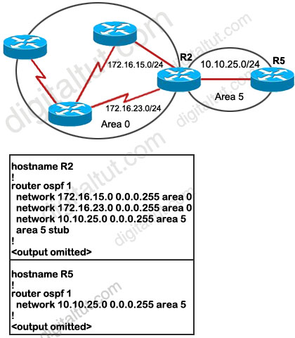
A. The Hello packets will be exchanged and adjacency will be established between routers R2 and R5.
B. The Hello packets will be exchanged but the routers R2 and R5 will become neighbors only.
C. The Hello packets will be dropped and no adjacency will be established between routers R2 and R5.
D. The Hello packets will be dropped but the routers R2 and R5 will become neighbors.
Answer: C
Explanation
Recall that in OSPF, two routers will become neighbors when they agree on the following: Area-id, Authentication, Hello and Dead Intervals, Stub area flag.
We must specify Area 5 as a stub area on the ABR (R2) and all the routers in that area (R5 in this case). But from the output, we learn that only R2 has been configured as a stub for Area 5. This will drop down the neighbor relationship between R2 and R5 because the stub flag is not matched in the Hello packets of these routers.
Question 8
When an OSPF design is planned, which implementation can help a router not have memory resource issues?
A. Have a backbone area (area 0) with 40 routers and use default routes to reach external destinations.
B. Have a backbone area (area 0) with 4 routers and 30,000 external routes injected into OSPF.
C. Have less OSPF areas to reduce the need for interarea route summarizations.
D. Have multiple OSPF processes on each OSPF router. Example, router ospf 1, router ospf 2
Answer: A
Question 9
When verifying the OSPF link state database, which type of LSAs should you expect to see within the different OSPF area types? (Choose three)
A. All OSPF routers in stubby areas can have type 3 LSAs in their database.
B. All OSPF routers in stubby areas can have type 7 LSAs in their database.
C. All OSPF routers in totally stubby areas can have type 3 LSAs in their database.
D. All OSPF routers in totally stubby areas can have type 7 LSAs in their database.
E. All OSPF routers in NSSA areas can have type 3 LSAs in their database.
F. All OSPF routers in NSSA areas can have type 7 LSAs in their database.
Answer: A E F
Explanation
Below summarizes the LSA Types allowed and not allowed in area types:
| Area Type |
Type 1 & 2 (within area) |
Type 3 (from other areas) |
Type 4 |
Type 5 |
Type 7 |
| Standard & backbone |
Yes |
Yes |
Yes |
Yes |
No |
| Stub |
Yes |
Yes |
No |
No |
No |
| Totally stubby |
Yes |
No |
No |
No |
No |
| NSSA |
Yes |
Yes |
No |
No |
Yes |
| Totally stubby NSSA |
Yes |
No |
No |
No |
Yes |
Popular LSA Types are listed below:
| LSA Type |
Description |
Details |
| 1 |
Router LSA |
Generated by all routers in an area to describe their directly attached links |
| 2 |
Network LSA |
Advertised by the DR of the broadcast network (does not cross ABR) |
| 3 |
Summary LSA |
Advertised by the ABR of originating area |
| 4 |
Summary LSA |
Generated by the ABR of the originating area to advertise an ASBR to all other areas in the autonomous system |
| 5 |
AS external LSA |
Used by the ASBR to advertise networks from other autonomous systems |
| 7 |
Defined for NSSAs |
Generated by an ASBR inside a Not-so-stubby area (NSSA) to describe routes redistributed into the NSSA |
Question 10
You are troubleshooting an OSPF problem where external routes are not showing up in the OSPF database. Which two options are valid checks that should be performed first to verify proper OSPF operation? (Choose two)
A. Are the ASBRs trying to redistribute the external routes into a totally stubby area?
B. Are the ABRs configured with stubby areas?
C. Is the subnets keyword being used with the redistribution command?
D. Is backbone area (area 0) contiguous?
E. Is the CPU utilization of the routers high?
Answer: A C
Explanation
A totally stubby stubby area cannot have an ASBR so it will discard this type of LSA (LSA Type 5) -> A is a valid check.
Each stubby area needs an ABR to communicate with other areas so it is normal -> B is not a valid check.
When pulling routes into OSPF, we need to use the keyword “subnets” so that subnets will be redistributed too. For example, if we redistribute these EIGRP routes into OSPF:
+ 10.0.0.0/8
+ 10.10.0.0/16
+ 10.10.1.0/24
without the keyword “subnets”
router ospf 1
redistribute eigrp 1
Then only 10.0.0.0/8 network will be redistributed because other routes are not classful routes, they are subnets. To redistribute subnets we must use the keyword “subnets”
router ospf 1
redistribute eigrp 1 subnets
-> C is a valid check.
We don’t need to care if area 0 is contiguous or not -> D is not a valid check.
CPU utilization cannot be the cause for this problem -> E is not a valid check.
For this question, please read our tutorial about OSPF LSA Types for more detail.